For microscope objectives having high numerical apertures, the optical properties and thickness of the medium lying between the front lens element and the specimen critically affect the calculations necessary to satisfy the aplanatic and sine conditions and otherwise to correct for image aberrations.

If homogeneous immersion objectives are designed to be used with the refractive indices and dispersion of the immersion oil, coverslip, and medium imbibing the specimen matching that of the objective front lens element, then the calculation is straightforward because all of the media can be considered an extension of the front lens element.
However, with non-immersion objectives, the coverslip can become a source of chromatic aberration, which increases with coverslip thickness and dispersion. Another optical artifact, spherical aberration, is also proportional to the thickness of the coverslip. In designing objectives that are not to be used with homogeneous immersion, one assumes the presence of a standard coverslip and other specific optical media between the front lens element and the specimen. As conditions depart from these designated specifications, spherical aberration and coma increase with the numerical aperture of the objective. This occurs because the difference between the tangent and the sine of the incident angle (which is responsible for departure from the sine condition needed to correct for these aberrations) becomes greater with longer numerical apertures.
When using oil immersion objectives, it may appear that coverslip thickness is of only limited concern, because its refractive index approximately matches that of the immersion oil. That is true when the specimen is mounted in Canada balsam or other mounting media with refractive indexes similar to that of the coverslip. However, it is no longer true when the specimen is mounted, for example, in physiological saline or other aqueous media whose refractive index is significantly different from that of the coverslip. In these conditions, even focusing through a thin layer of water only 10 microns thick can lead to significant aberrations and a point spread function (PSF) that is no longer symmetrical above and below the focal plane. This is because oil immersion objectives are designed assuming that the specimen slide is homogeneously immersed. Unless the specimen region is adjacent to the coverslip (even in an aqueous environment), optical assumptions employed to calculate the aberration corrections are no longer valid.
Coverslip Correction Collars
Exploring how an entire lens group is translated within the objective barrel to compensate for cover glass thickness variations.
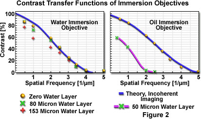
Start Tutorial »Once this characteristic behavior of oil immersion objectives was recognized, microscope manufacturers began to produce well-corrected water immersion objectives (around 1994). Plan Apo water immersion objectives equipped with correction collars have a numerical aperture around 1.2, and (even though they have a smaller numerical aperture than their oil immersion counterparts) are able to overcome the inherent limitations of imaging through aqueous solutions (see Figure 2). The latest water immersion objective designs can now focus through approximately 200 microns of aqueous media and still retain excellent correction. Unfortunately, the price of these objectives is very high, and the image can still degrade when focusing deep within refractile tissue or cell elements.

Contrast transfer values of a 60x/1.2 numerical aperture water immersion and a 60x/1.4 numerical aperture oil immersion objective (both Plan Apochromats), measured with and without layer of water between the coverslip and test gratings are presented in Figure 2. The graphs demonstrate that the water immersion objective performs at the theoretical limit of contrast transfer even with water layers as thick as 153 microns, whereas the contrast transfer function of the oil immersion objective is dramatically reduced and the resolution limit is cut by half when the test grating is imaged through a 50-micron thick water layer. The continuous lines are theoretically calculated contrast transfer functions of aberration-free objective lenses of corresponding numerical aperture at a wavelength of 546 nanometers.

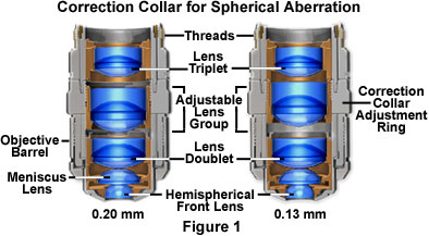
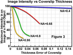
For objectives designed to be used with a standard coverslip thickness and refractive index/dispersion (0.17 millimeters and n(D) = 1.515), departure from the standard thickness is not overly critical when the objective has a numerical aperture of 0.4 or less (as presented in Table 1). However, for high numerical aperture non-homogeneous immersion objectives, the problem becomes especially critical so that a departure of coverslip thickness of even a micrometer or two degrades the image with high-dry objectives of numerical aperture 0.65 or greater. This concept is illustrated in Figure 3, which presents the calculated maximum intensity in the image of a point object versus the deviation of the coverslip thickness, from the ideal value of 0.17 millimeters, as a function of objective numerical aperture. To compensate for such error, well-corrected, high-dry objectives are equipped with correction collars that can be utilized to adjust the spacing of their intermediate lens elements according to the coverslip thickness. In the same manner, objectives designed for viewing through layers of silicone or plastic, or of different immersion media (water, glycerol, oil), are equipped with correction collars.
Performance Reduction with Coverslip Thickness Variation
| NumericalAperture | 0.01 mm Deviation | 0.02 mm Deviation |
|---|---|---|
| 0.30 | none | none |
| 0.45 | none | none |
| 0.70 | 2 percent | 8 percent |
| 0.85 | 19 percent | 57 percent |
| 0.95 | 55 percent | 71 percent |
Table 1
The standard thickness for cover glasses is 0.17 millimeters, which is designated as a number 1½ cover glass. Unfortunately, not all 1½ cover glasses are manufactured to this close tolerance and many specimens have media between them and the cover glass. Compensation for cover glass thickness can be accomplished by adjusting the mechanical tube length of the microscope, or (as previously discussed) by the utilization of specialized correction collars that change the spacing between critical lens elements inside the objective barrel. The correction collar is adjusted to compensate for these subtle differences and ensure optimum objective performance. Proper application of objective lenses with correction collars demands that the microscopist is experienced and alert enough to reset the collar using appropriate image criteria. In most cases, focus may shift and the image may wander during adjustment of the correction collar. Use the steps listed below to make small incremental adjustments to an objective's correction collar while observing changes in the specimen image.
- Position the correction collar so that the indicator mark on the objective barrel coincides with the 0.17-millimeter scale mark engraved on the collar housing.
- Place a specimen on the stage and focus the microscope on a small specimen feature.
- Rotate the correction collar very slightly and re-focus the objective to determine if the image has improved or degraded. Due to the fact that most specimen preparations suffer from cover glass/media sandwiches that are too thick, start the rotation experiment by trying larger compensation values (0.18-0.23) first.
- Repeat the previous step to determine if the image is improving or degrading as the correction collar is turned in a single direction.
- If the image has degraded, follow the same steps and rotate the correction collar in the opposite direction (toward lower values) to find the position offering optimum resolution and contrast.
Figure 1 illustrates an example of a 60x objective having a numerical aperture of 0.85 equipped with a correction collar for focusing at the surface or through a coverslip up to 1.5 millimeters in thickness without altering the focal setting of the lens system. The adjustable lens group in the center of the optical train is a cemented triplet that can be re-positioned to accommodate variations in coverslip thickness.