Field Curvature Aberrations
Optical Aberrations - Field Curvature Aberrations - Java Tutorial
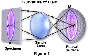
A simple lens focuses image points from an extended flattened object, such as a specimen on a microscope slide, onto a spherical surface resembling a curved bowl. The nominal curvature of this surface is the reciprocal of the lens radius and is referred to as the Petzval Curvature of the lens. Curvature of field in optical microscopy is a common and annoying aberration that is familiar to most experienced microscopists.
The tutorial initializes with an image of the specimen (as seen through the microscope) appearing in a window on the left-hand side of the applet. Beneath the image window is a pull-down menu labeled Choose A Specimen, which can be used to select a new specimen. The Image Position slider is utilized to control the tutorial by shifting the focal plane along the optical axis of the virtual lens system illustrated as a ray trace pattern on the right-hand side of the applet window. The initial position of the slider is just to the left of center, in the area of best overall focus. When the slider is moved farther to the left, the focal plane is shifted to the center of the Petzval surface in the optical path, and the microscope image and point spread function diagram simultaneously change to illustrate the effect of field curvature aberration. Moving the slider to the right shifts the focal plane to the edges of the Petzval surface and produces corresponding changes in the microscope image and point spread function. A grid pattern, positioned adjacent to the microscope image and labeled Film Plane, also illustrates the effect of field curvature on a virtual film plane or CCD surface.
When visible light is focused through a curved lens, the image plane produced by the lens will be a curved Petzval surface as illustrated in Figure 1. Notice that there are two focal planes (among many not shown) near the Petzval surface that are labeled A and B. The image can be focused over a large number of focal planes positioned between A and B to produce either a sharp focus on the edges or in the center of the image. When the specimen is viewed in the eyepieces (oculars) of a microscope, it either appears sharp and crisp in the center or on the edges of the viewfield but not both. This occurs because the greater distance of off-axis points from the lens center results in closer off-axis image points. Normally, this is not a serious problem when the microscopist is routinely scanning samples to observe their various features. It is a simple matter to use the fine focus knob to correct small deficiencies in specimen focus. However, for photomicrography, field curvature can be a serious problem, especially when a portion of the photomicrograph is out of focus.

This concept is illustrated in the tutorial using several photomicrographs representing a variety of illumination techniques. When the Image Position slider is moved to the far left, the central portion of the image is in focus with the outer portions of the image becoming very blurred. It is not possible to distinguish any minor structural details present at the edges of the viewfield. Alternatively, when the slider is moved to the far right, the opposite effect occurs with the central portion of the image becoming out of focus and the edges coming into sharp focus. The middle portion of the slider range represents the best compromise between center and edge focus. This position would be the focus that a microscopist would be forced to use for photomicrography with optics in this state.
Curvature of field can be tolerated when just scanning samples, but it is disastrous when one is trying to produce quality photomicrographs. In the early days of microscopy before corrected lenses were enjoying widespread use, photomicrographers would often restrict the area recorded on film to the focused central area of the viewfield, thus obscuring the blurred edges. This can be easily accomplished by inserting a projection lens in the phototube to reduce the amount of viewfield available for the camera. Another method is to use a bellows extension on the camera to increase the camera film distance from the projection lens until only the central portion of the viewfield is visible.
Prior to the advent of flat-field objectives by the Carl Zeiss corporation in the late 1930s, the effective flat area of the field at the intermediate image plane was only 10 to 12 millimeters. Modern microscopes deal with field curvature by correcting this aberration using specially designed objectives. These highly-corrected objectives have been named plan or plano (for flat-field) and are the most common type of objective in use today, providing ocular fields ranging between 18 and 26 millimeters and capable of producing sharp image detail from center to edge. This optical improvement has been obtained at the expense of increased objective complexity and cost, and often reduced transmission. In fact, flat-field correction has only become practical after the introduction of antireflection coatings.
Plan objectives are also corrected for other optical artifacts such as spherical and chromatic aberrations. In the case of a plan objective that also has been mostly corrected for chromatic aberration, the objective is referred to as a plan achromat. This is also the case for fluorite and apochromatic objectives, which have the modified names plan fluorite and plan apochromat, respectively.
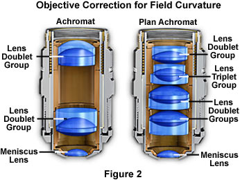
Adding field curvature lens corrections to an objective that has already been corrected for other monochromatic (Seidel) and polychromatic optical aberrations can often add a significant number of lens elements to the objective. For example, the typical achromat objective has two lens doublets and a thick meniscus or hemispherical lens, yielding a total of five lens elements, as shown on the left-hand side of Figure 2. In contrast, a comparable plan achromat objective has three doublets, a lens triplet, a meniscus lens and hemispherical front lens, for a total of eleven lens elements, making it considerably more difficult to fabricate. Cut-away diagrams illustrating both of these objectives are presented in Figure 2. As we have seen, the number of lens elements increases as lenses are corrected for spherical errors as well as chromatic and field curvature aberrations. Unfortunately, as the number of lens elements increases so does the cost of the objective.

Sophisticated plan apochromatic objectives that correct for spherical, chromatic, astigmatic, comatic, distortion, and field curvature aberrations can contain as many as eighteen to twenty separate lens elements, making these objectives the most expensive and difficult to manufacture. Plan apochromatic objectives can cost upward of $3,000 to $4,000 each for high-magnification units that also have a high numerical aperture. For many photomicrography applications, however, it is not absolutely necessary to have the best correction, although this is heavily dependent upon the specimen and the desired magnification range. When cost is important, it is often wise to select more modestly priced plan fluorite objectives that have a high degree of correction, especially the more modern versions. These objectives provide crisp and sharp images with minimal field curvature, and will be sufficient for over 90 percent of photomicrography applications.
Field curvature is very seldom totally eliminated, but it is often difficult to detect edge curvature with most plan-corrected objectives and it does not show up in photomicrographs. This artifact is more severe at low magnifications and can be a serious problem with stereo microscopes, where an apparent east-west curvature is caused primarily by the stereo angle or tilt of the twin beam paths in relation to a flat object. Manufacturers have struggled for years to eliminate field curvature in the large objectives found in stereo microscopes. In the past ten years companies like Nikon, Olympus, Zeiss, and Leica have made great strides in the quality of optics used to build stereo microscopes and, while the artifacts and aberrations have not been totally eliminated, the high-end models are now capable of producing superb photomicrographs.
Sorry, this page is not
available in your country.