Not Available in Your Country
Sorry, this page is not
available in your country.
Overview
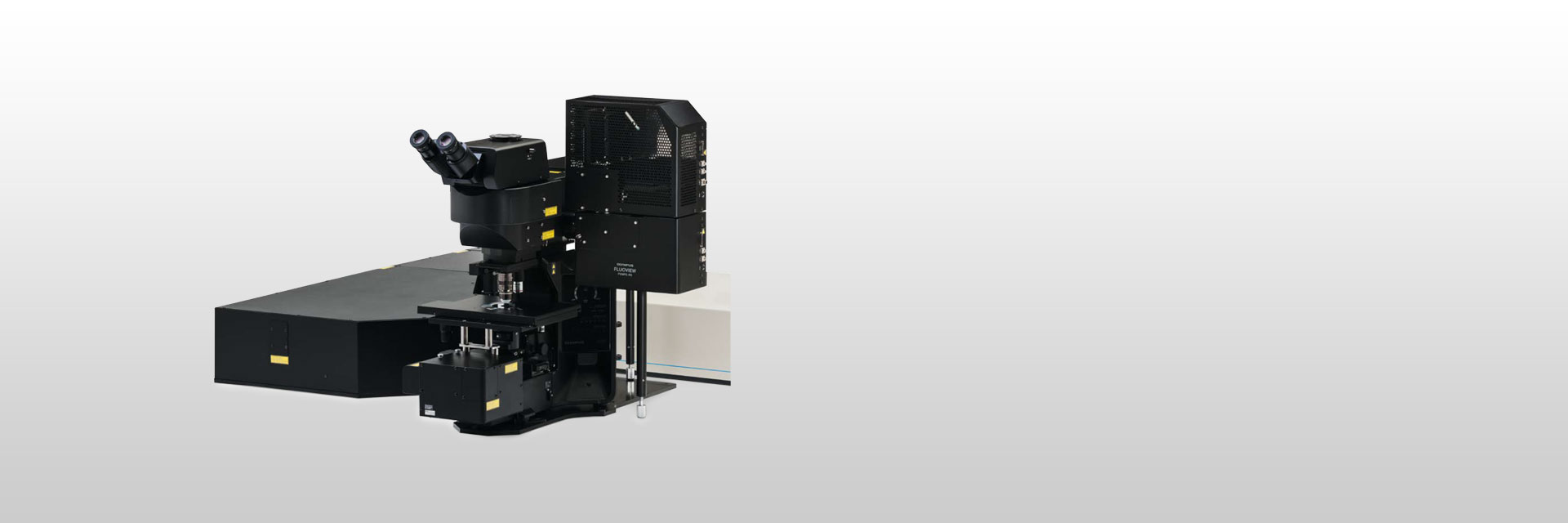 | See More Detail at DepthDesigned for deep imaging in biological specimens, the FVMPE-RS multiphoton microscope helps reveal how cells function and interact within living tissue. This product has been discontinued, check out our current product |
|---|
High-Sensitivity, High-Resolution Deep Multiphoton ImagingThe FVMPE-RS multiphoton microscope employs advanced technology and optical design to enhance sensitivity and resolution during deep imaging.
|
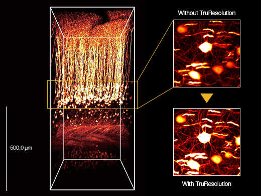
3D reconstructed image of an in vivo mouse brain (Thy1-YFP-H mouse, sensory cortex) acquired using a TruResolution objective with an auto adjustment function (left) and maximum projection images acquired at an approximately 600 μm depth. Images acquired without (top right) and with (bottom right) the auto adjustment function. Images were acquired at the RIKEN BSI-Olympus Collaboration Center, courtesy of Dr. Hiromu Monai, Dr.Hajime Hirase, and Dr. Atsushi Miyawaki. |
Related Videos
Zebrafish embryo blood flow.
| High-Speed Imaging for Fast, Dynamic Cellular ProcessesHigh-speed resonant scanning and high-resolution linear scanning are standard.
|
|---|
Multiwavelength Excitation for Broader Spectral CoverageThe FVMPE-RS imaging platform supports a dual wavelength infrared pulsed laser or two independent tunable infrared lasers for multichannel, multiphoton excitation imaging.
|
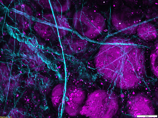
Third harmonic generation imaging of porcine adipose tissue. Unlabeled porcine adipose tissue was irradiated with femtosecond laser at 1250 nm, second harmonic is detected from collagen fibers at 625 nm and third harmonic from lipid interfaces at 416 nm. |
| Optional Features for Advanced ApplicationsThe FVMPE-RS multiphoton microscope is a modular platform, enabling you to easily upgrade your system as your research needs grow. Options include:
|
|---|
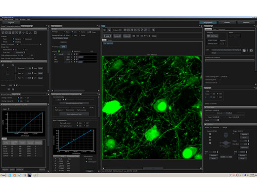
Intuitive Software Optimized for Multiphoton ObservationThe customizable software layout gives you more flexibility, increasing your efficiency:
Online analysis and image processing, including spectral unmixing and 3D rendering, come standard. |
|
3 Microscope Frame Options |
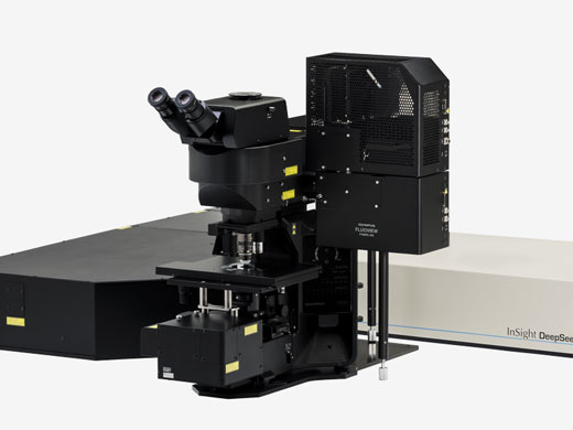
Upright Microscope System — For in vivo and in vitro multiphoton microscopyThe large stage clearance and long focus stroke of the standard upright frame accommodate a wide range of specimens, from tissue slices to live mice and other small animals. |
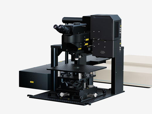
Gantry Microscope System — For in vivo observations that require more spaceThe 355 mm height clearance between the objective and the base plate facilitates in vivo observations that require large apparatus, such as behavioral imaging in awake mice. |
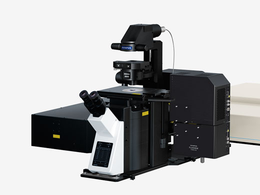
Inverted Microscope System — For in vitro observation of 3D cell (spheroid) and tissue culturesThe inverted frame provides a stable platform for time-lapse imaging of thick living specimens, especially tissue cultures and 3D spheroid and organoid cell cultures. This configuration is also useful for intravital imaging of organs and tissues through a body window in a small animal. |
Applied Technologies
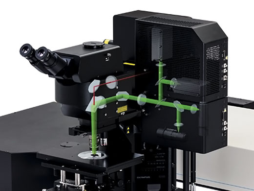
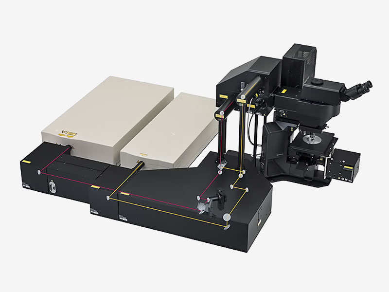 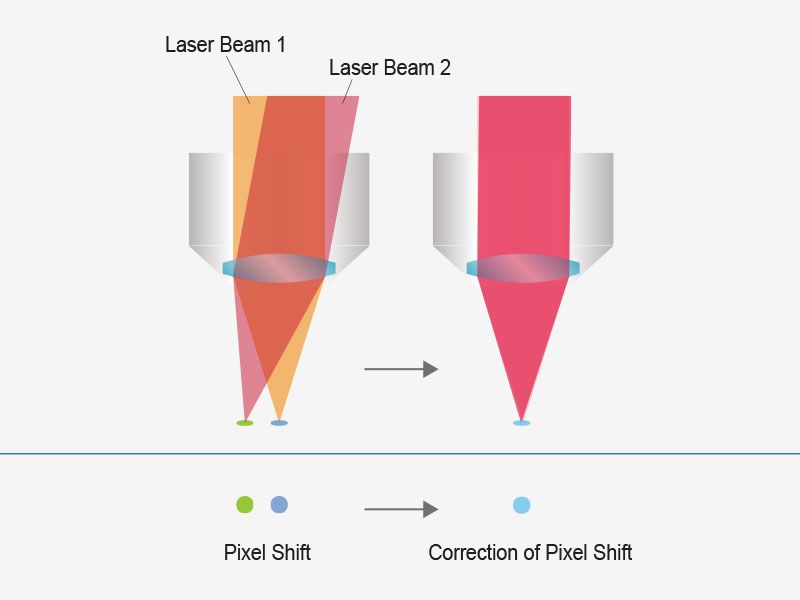 | User-Friendly, Accurate Imaging with Automated Laser AlignmentLaser drift caused by wavelength tuning, temperature fluctuation, and other sources of cavity shift can cause a misalignment of the excitation beam in typical systems. The FVMPE-RS multiphoton microscope maintains precise 4-axis laser alignment of the excitation beam into the scanner unit, even in the face of laser drift, simplifying system upkeep. The beam position and angle are automatically adjusted to deliver higher laser power and consistent pixel registration. If your system has two excitation laser lines, this feature maintains co-alignment between the beams, helping eliminate co-registration errors between channels. |
|---|
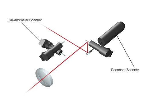
High-Speed Scanning at up to 438 Frames-per-SecondThe fast resonant scanner and linear galvanometer scanner provide high-speed and high-resolution imaging in a single system. With capture rates of up to 438 fps at 512 × 32 pixels or 30 fps at 512 × 512 pixels across the full field of view (FN 18), you can:
|
|
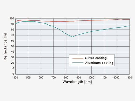
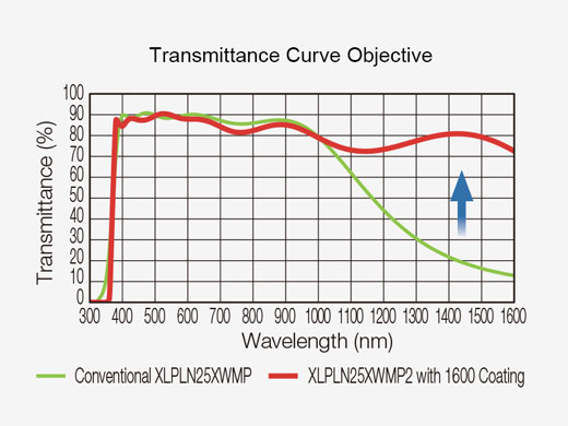
| Efficient Laser TransmissionSilver-coated scanner mirrors help deliver more laser power to your sample for brighter images. Increased reflectance in the near-infrared range compared to conventional aluminum-coated mirrors is especially advantageous for deep in vivo experiments. |
|---|
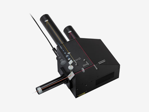
Detector Options Maximize Fluorescence Imaging PerformanceAcquire high signal-to-noise ratio (SNR) images from faint fluorescence with high-sensitivity gallium arsenide phosphide (GaAsP) photomultiplier tube (PMT) detectors. They offer a higher quantum efficiency than standard multialkali (MA) PMTs and have fanless cooling to further improve the SNR. If you work with brightly emitting samples, you can combine the high SNR of GaAsP detector with the wider dynamic range of MA detector. For greater light efficiency, the system’s non-descanned detection path features large-area optics to better capture scattered fluorescence photons and make full use of the wide collection capacity of our multiphoton objectives. |
|
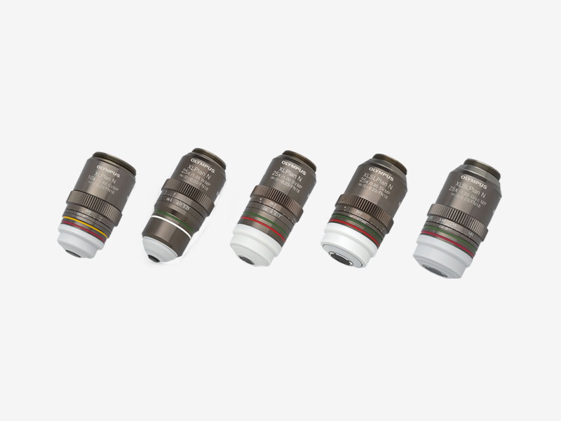
MPE Objectives Designed for Deep Imaging
|
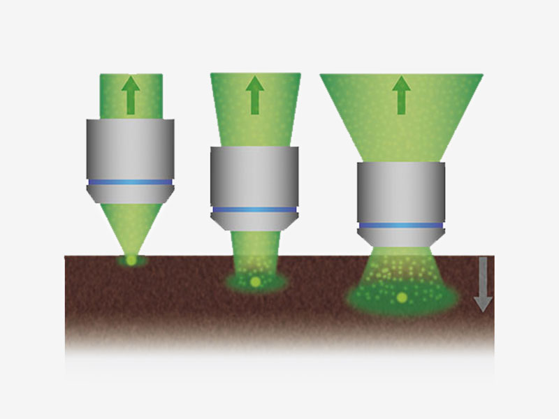
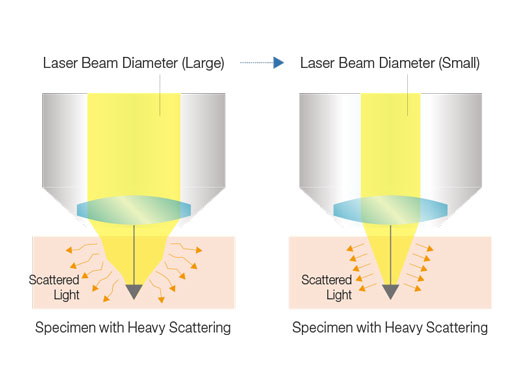
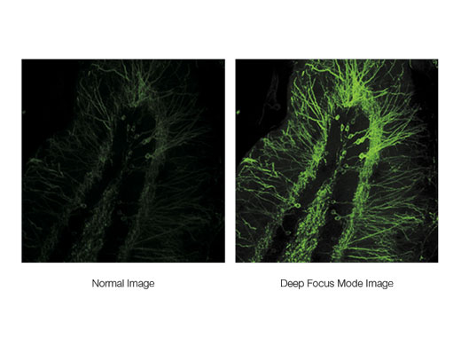
Maximize Signal with Deep Focus ModeDeep focus mode adjusts the diameter of the laser beam based on the laser scattering conditions. For in vivo specimens with heavy laser scattering, the beam is narrowed so that more excitation photons reach deeper within your sample, helping produce brighter images. |
|
|
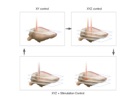
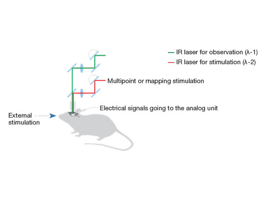
| Independent Photostimulation ControlFor precise microsecond photostimulation and photobleaching experiments, add:
Arbitrary stimulation regions of interest (ROI) can be defined independent of an imaging ROI. Random access multipoint sequential stimulation is also available when greater speed is required. On systems with two IR imaging lines, the SIM scanner enables simultaneous multiphoton stimulation and imaging. |
|---|
Microsecond Timing for Electrophysiology and OptogeneticsA hardware sequencer provides microsecond precision timing for stimulation and triggering events. Stimulation can be spatially and temporally synchronized to the imaging scan, facilitating the capture of fast response dynamics at precise locations. For electrophysiology and optogenetics, this could mean the difference between distinguishing a synchronous versus an asynchronous stimulus response. For acquisitions lasting two weeks or longer or experiments with complex procedures that require switching between imaging tasks, the sequence manager software module maintains millisecond precision, providing high-quality data in demanding in vivo and in vitro experiments. Learn more about multi-dimensional and multi-area time-lapse imaging |
|
Solutions
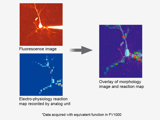
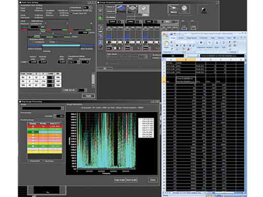
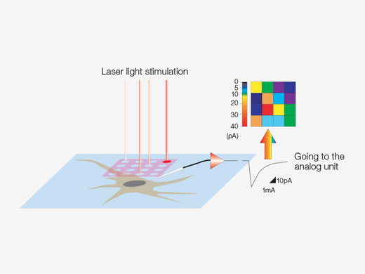
Synchronize Electrophysiological Data and Laser Light Stimulation with the Analog UnitAnalog inputs and digital TTL I/O are available to support electrophysiology experiments. The analog input unit records external voltage signals as image data. Light-stimulated electrical signals measured with patch clamps can be synchronized with image capture and displayed as a pseudocolor intensity overlay. Learn more about the Analog Unit Multipoint mapping advanced software (MMASW) enables precise light stimulation of multiple arbitrarily selected points or points in a rectangular region of interest (ROI) for mapping scans. It can simultaneously record electrical voltage signals from the patch clamping system.
Learn more about the Multi Point and Mapping Software Module |
|
*Multicolor point-by-point laser control supported using SIM scanner with multiple lasers for mixed ChR2 and NpHR experiments. |
| Create 3D Stimulation Reaction MapsSpecialized mapping scans utilize a pseudorandom sequence to deliver more precise spatial reaction maps when measuring electrophysiological response to optical stimulation. Direct electrical patch clamp recordings and fluorescence signals from calcium or voltage indicators can be overlaid on a high-resolution image. Intensity thresholds can be used to define a high-speed multipoint scan of the most active regions. This can be extended to 3D reaction maps with an optional piezo Z drive. |
|---|
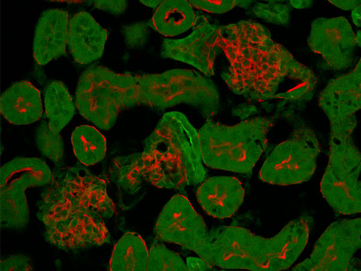
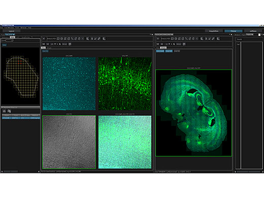
Combine a Wide Field of View with High ResolutionSee your entire specimen at high resolution and in wider context with the multiarea time lapse (MATL) function:
|
Image data courtesy of Urs Ziegler and Jose Maria Mateos, Center for Microscospy and Image Analysis, University Zurich. Mouse line L15 kindly provided by Pico Caroni, FMI, Basel. |
|---|
Software
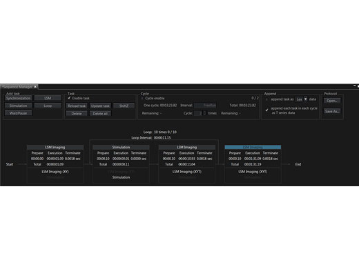
Precisely Control Your ExperimentsThe sequence manager makes it easy to coordinate experiments. You can easily organize and expedite complex protocols with precise timing, including:
You can save and reload protocols for consistent experiment execution. |
|
Separate Overlapping Channels with Spectral DeconvolutionClosely overlapping fluorescence spectra can complicate biological studies that look at multiple labels simultaneously. Now, overlapping spectral channels can be separated using spectral deconvolution based on a blind unmixing algorithm or previously saved multichannel profiles. Crosstalk between the channels can even be eliminated during image acquisition through live processing. |
Normal Mode
Spectral overlap of red and green fluorescence causes cross-talk between the channels during normal acquisition. | Live Unmixing Mode
Live unmixing mode applies spectral deconvolution during image acquisition to better separate distinct fluorophores. |
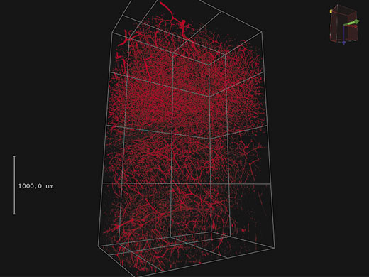
3D RenderingLarge amounts of Z-stack data can be rendered into a 3D display. Important views can be registered as key frames, making it easy to create animated views of 3D images that zoom and transition to different camera angles. |
4 mm 3D stack on blood vessel labeled with Texas red in mouse brain.
|
(Left) Raw 30 fps data acquired at low laser power (0.05%, 488 nm).
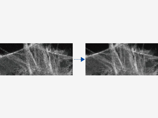
| Rolling Average ProcessingHigh-speed scanning at low laser power to avoid phototoxicity can decrease the signal-to-noise ratio. With rolling average post-processing, you have the flexibility to adjust high-speed time-lapse images while maintaining the time scale and keeping the original data. |
|---|
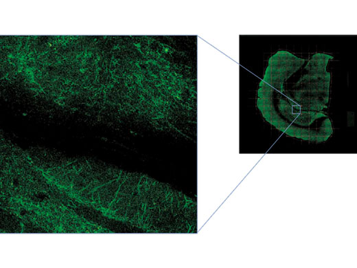
Macro-to-Micro ObservationThe use of a high-numerical aperture (NA) objective, motorized stage, and Olympus software enables mosaic imaging:
|
|
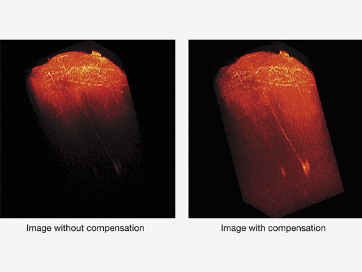
| Depth-Brightness CompensationWhen observing thick specimens, images can get darker as the focal point goes deeper. But with Bright Z depth-brightness compensation, detector sensitivity and laser power are continually adjusted to maintain consistent brightness. This function complements the dynamic TruResolution objectives that also automatically adjust spherical aberration compensation with depth. |
|---|
Expanded Analysis FunctionsThe FVMPE-RS imaging platform’s software is integrated with Olympus cellSens image analysis software, expanding the system’s analytical capabilities. Optional features include:
Optional NoviSight 3D analysis software is also available. Learn more about the cellSens imaging software |
Specifications
FLUOVIEW FVMPE-RS |
| One Laser System | Dual Lines System | Twin Lasers System | ||
|---|---|---|---|---|
| Unit | Qualified IR Pulsed Lasers with Negative Chirp for Multiphoton Excitation | Spectra-Physics products: MAITAI HPDS-OL: 690 nm–1040 nm MAITAI eHPDS-OL: 690 nm–1040 nm INSIGHT X3-OL: 690 nm–1300 nm INSIGHT X3 DUAL/DUALC-OL: 680 nm–1300 nm + 1045 nm Coherent products: Chameleon Vision I Olympus: 680 nm–1080 nm Chameleon Vision II Olympus: 680 nm–1080 nm Chameleon Vision S Olympus: 690 nm–1050 nm | ||
| Main IR Pulsed Laser |
MAITAI HPDS-OL
MAITAI eHPDS-OL INSIGHT X3-OL Chameleon Vision I Olympus Chameleon Vision II Olympus Chameleon Vision S Olympus |
INSIGHT X3 DUAL-OL
INSIGHT X3 DUALC-OL |
MAITAI HPDS-OL
MAITAI eHPDS-OL INSIGHT X3-OL Chameleon Vision I Olympus Chameleon Vision II Olympus Chameleon Vision S Olympus | |
|
Additional IR Line Laser:
Use as second imaging line/laser or for simultaneous stimulation (optional SIM scanner) | – |
1045 nm fixed line from
INSIGHT X3 DUAL /DUALC-OL |
MAITAI HPDS-OL
MAITAI eHPDS-OL Chameleon Vision I Olympus Chameleon Vision II Olympus Chameleon Vision S Olympus | |
| Automatic Introduction Optic |
Introduction optic with AOM attenuation
(0%–100%, 0.1% increments) Including fully automated beam expander, XY shifter and two-axis angle alignment. (4-axis quadralign autoalignment optics) Direct coupling to laser port of scanning unit. |
Introduction optic with 2 sets of AOM attenuation (0%–100%, 0.1% increments)
Including 2 sets of fully automated beam expanders, XY shifter and two-axis angle alignment. (4-axis quadralign autoalignment optics) Direct coupling to laser port of scanning unit. | ||
| IR Laser Combining Optic | – | Motorized light path switcher with DM900, DM1000R, DM1100 to combine two IR wavelength for imaging | ||
| Optional Visible Light Laser for Stimulation | 405 nm/50 mW, 458 nm/20 mW, 588 nm/20 mW laser source with AOTF attenuation. 0%–100%, 0.1% increments, < 2 μs rising time | |||
| Scanning Unit | Scanning Method | Light deflection via 2 silver-coated galvanometer scanning mirrors, or silver-coated resonant scanning mirror | ||
| Scanning Speed |
Galvanometer scanner (normal imaging): 512 × 512 with 1.1 s–264 s, pixel time: 2 μs–1000 μs
Resonant scanner (high-speed imaging): 30 fps at 512 × 512, 438 fps at 512 × 32 | |||
| Scanning Mode | XY, XYZ, XYT, XYZT, free line, XZ, XT, XZT, PointT | |||
|
Galvanometer Scanner
(Normal Imaging) |
Galvanometer ROI scanning: rectangle clip, ellipse, polygon, free area, line, free line, and point
Zoom: 1.0x–50.0x with 0.01x increments, supports 0°–360° rotation and pan Scanning Field Number: 18 Image Size: 64 × 64–4096 × 4096 | |||
|
Resonant Scanner
(High-Speed Imaging) |
Resonant ROI scanning: rectangle clip, line
Zoom: 1.0x–8.0x with 0.01x increments Scanning field number:18 Image size: 512 × 512 | |||
| Optical Coating | IR support optic with 1600 coating | |||
| Non-descanned MPE Imaging Detectors |
Reflected detection: 2 or 4 channel configuration: 2 PMT configuration, 4 PMT configuration or 2 PMT + 2 cooled GaAsP-PMTs
Transmitted detection: 2 PMT unit with high NA condenser | |||
| Transmitted-Light Detector | Module with integrated external transmitted light photomultiplier detector and 100 W halogen lamp, motorized switching, fiber adaptation to microscope frame | |||
| Z-Drive |
Integrated motorized focus module of the microscope, minimum increment 0.01 μm
Optional: highly rigid piezo nosepiece*1 | |||
| Optional Simultaneous Stimulation Scanner |
Highly synchronized simultaneous stimulation scanner, including a set of galvanometer scanner, VIS and IR laser port.
ROI scanning: rectangle clip, ellipse, polygon, tornado, free area, line, free line, and point. | |||
| Optional Analog and Digital in/out Box | 4-channel analog signal input, 6-channel digital TTL trigger input, 5-channel digital TTL trigger output. Scanner timing output | |||
| Operation Environment | Room temperature: 20°C–25°C, humidity: 75% or less at 25°C, requires continuous (24-hour) power supply | |||
| Size of Anti-Vibration Table |
1500 mm × 1650* mm
*1800 mm with inverted microscope system |
1500 mm × 1650* mm
*1800 mm with inverted microscope system | 1500 mm × 2000 mm | |
| Software | Basic Feature |
Dark room matching GUI design. User arrangeable layout.
Acquisition parameter reload features. Hard disk recording capability, Adjust laser power and HV with Z-stack acquisition. Z-stack with alpha blending, Maximum intensity projection, Iso-surface rendering | ||
| IR Laser Control | Fully integrated IR laser wavelength control and Deep Focus mode | |||
| Optional Motorized Stage software |
XY motorized stage control. Map image acquisition for easy target locating. Tiling acquisition and software image stitching.
Define multiple area for time lapse imaging. | |||
| Optional Mapping and Multiple Point Stimulation Software |
Multiple point stimulation and data acquisition software. Mapping multiple point stimulation to generate reaction map.
Filtering feature to select points. Multiple point stimulation. Single or repeat stimulation. Each point independent stimulation wavelength selection. | |||
|
Optional Sequence
Manager |
Advanced programmable software to define multiple imaging/stimulation tasks and execute by hardware sequencer.
Minimum gap 100 ms delay between tasks. | |||
| Optional Auto Compensation Software |
Automatic spherical aberration compensation software.
Control of objective lens with auto spherical aberration compensation function. Auto adjustment of motorized correction collar to find the best position at certain observation depth. Auto adjustment of correction collar along with Z movement. | |||
*1 Not available in some areas. |
TruResolution Objectives |
| FV30-AC10SV | FV30-AC25W | |
|---|---|---|
| Magnifications | 10 | 25 |
| NA | 0.6 | 1.05 |
| W.D. | 8 mm | 2 mm |
| Cover Glass Thickness | 0 mm–0.23 mm | 0 mm–0.23 mm |
| Immersion Liquid | SCALEVIEW-A2 (water, silicone oil, and normal oil available) | Water |
| Special Features | Auto compensation, optimized for multiphoton imaging | Auto compensation, optimized for multiphoton imaging |
| Dimensions (W × D × H) | 56 mm × 106.5 mm × 95 mm | 56 mm × 106.5 mm × 101 mm |
| Weight | Approx. 1kg | Approx. 1kg |
