Birefringent Crystals in Polarized Light
Birefringent Crystals in Polarized Light - Java Tutorial
In order to examine how birefringent anisotropic crystals interact with polarized light in an optical microscope, the properties of an individual, isolated crystal can be considered. The specimen material in this tutorial is a hypothetical tetragonal birefringent crystal having an optical axis oriented in a direction that is parallel to the long axis of the crystal. Light entering the crystal from the polarizer will be traveling perpendicular to the optical axis of the crystal, regardless of the crystal orientation with respect to the polarizer and analyzer transmission axes. The virtual microscope viewport presents the crystal as it would appear in the eyepieces of a microscope under crossed-polarized illumination as it is rotated around the microscope optical axis.
To operate the tutorial, use the Stage Rotation Angle slider control to simulate the rotation of the crystal through 360 degrees on a circular microscope stage between crossed polarizers. The initialization state of the tutorial is 211 degrees of rotation with the long axis of the crystal oriented Northwest-Southeast to the polarizer and analyzer transmission planes. As the slider is translated, the virtual microscope stage rotates either clockwise (slider to the right) or counterclockwise (slider to the left), causing the crystal to rotate with it. At the 45-degree position, the crystal is at the optimum angle with respect to both the polarizer and analyzer to display maximum birefringence (this effect also occurs at 135, 225, and 315 degrees). The radio buttons simulate the insertion of a first-order (full wavelength) retardation plate into the light path, with the slow (Z) axis oriented at a 45-degree angle with respect to the transmission axes of the polarizer and analyzer.
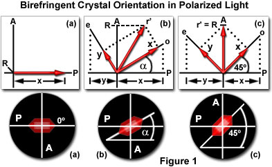
Figure 1 illustrates the virtual crystal as it would appear through the eyepieces of a microscope under crossed-polarized illumination. In this figure, the axis of the microscope polarizer is indicated by a P and is oriented in an East-West direction. The light vibration plane axis of the analyzer is indicated by an A and is oriented in a North-South direction. These axes are perpendicular to each other and result in a totally dark field when viewed through the eyepieces without the insertion of birefringent crystals. Figure 1(a) illustrates an anisotropic birefringent crystal that has the long (optical) axis oriented parallel to the direction of the polarizer.

In this case, light passing through the polarizer, and subsequently through the crystal, is vibrating in a plane that is parallel to the direction of the polarizer. There is no contribution from light passing through the analyzer (because of the single direction of light vibration—parallel to the polarizer) resulting in the crystal being very dark and almost invisible. In Figure 1(a) the crystal is not totally extinct (as it would be between crossed polarizers) but passes a small portion of red light. This was done for illustration purposes only to allow visitors to note the position of the crystal.
Microscopists classically refer to this orientation as being a position of parallel extinction for the crystal. This observation is important in determining the refractive indices of anisotropic materials with a polarizing microscope. By removing the analyzer in a crossed polarizing microscope, the single permitted direction of vibration of light passing through the polarizer interacts with only one electric component in the birefringent material (crystal). This allows segregation of a single refractive index for measurement. The remaining refractive index of the material can then be measured by rotation of the polarizer by 90 degrees.
The situation is very different in Figure 1(b), where the long (optical) axis of the crystal is now positioned at an angle (α) with respect to the polarizer. In this case, a portion of the light received through the polarizer is passed on to the analyzer. To obtain a quantitative estimate of the amount of light passing through the analyzer, we can apply simple vector analysis to solve the problem. The first step is to find the contributions from the polarizer to o and e (see Figure 1(b); these are arbitrary designations for the ordinary (o) ray and extraordinary (e) ray). This is accomplished by dropping projections of the vectors onto the axis of the polarizer. This method assumes the arbitrary value of 1 for both o and e, which are proportional to the actual intensities of the ordinary and extraordinary ray. The contributions from the polarizer for o and e are illustrated with red arrows designated by x and y on the polarizer axis (P) in Figure 1(b). These lengths are then measured on the vectors o and e (also shown as red arrows on the vectors) to produce the resultant r', which is projected onto the analyzer axis (A) as the absolute value R. As discussed above, the value of R on the analyzer axis is proportional to the amount of light passing through the analyzer. When R has a positive value, some of the light from the polarizer has passed through the analyzer and the birefringent crystal displays an intermediate degree of brightness.
The maximum brightness for a birefringent material is shown when the long (optical) axis of the crystal is oriented at a 45 degree angle to both the polarizer and analyzer, as illustrated in Figure 1(c). Dropping the projections of the vectors o and e onto the polarizer axis (P) determines the contributions of the polarizer to these vectors. When these projections are then measured on the vectors (again with red arrows on the vectors), and completing the rectangle to compute the resultant value r', we find the maximum possible contribution to light passed through to the analyzer in this system. This method will work for the orientation of any crystal with respect to the polarizer and analyzer axis because o and e are always at right angles to each other, with the only difference being the orientation of o and e with respect to the crystal axes.
このページはお住まいの地域ではご覧いただくことはできません。