Comatic Aberrations
Optical Aberrations - Comatic Aberrations - Java Tutorial
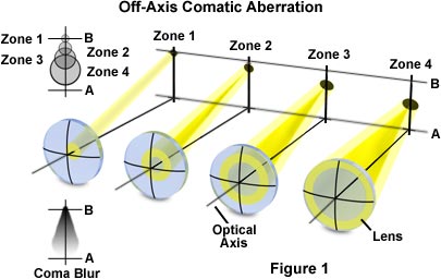
Comatic aberrations are similar to spherical aberrations, but they are mainly encountered with off-axis light fluxes and are most severe when the microscope is out of alignment. When these aberrations occur, the image of a point is focused at sequentially differing heights producing a series of asymmetrical spot shapes of increasing size that result in a comet-like (hence, the term coma; Figure 1) shape to the Airy pattern.
When the tutorial initializes, an oblique view of an aberration-free three-dimensional Airy diffraction pattern (termed a point spread function) appears in the center of the applet window along with a cross section of the pattern as it appears in the image plane. To the left of the Airy pattern is the image formed by the microscope and a slider labeled Off-Axis Distance. On the right-hand side of the applet window is a ray trace diagram that plots changes in the image focal point size and location as a function of off-axis distance. As the slider is slowly moved to the right, the microscope image acquires an increasing amount of comatic aberration and the shape of the Airy pattern transforms into an intensity distribution typically found with this type of aberration. Simultaneously, the ray trace diagram first displays on-axis light rays that move to a series of off-axis focal points having differing transverse magnification.
Coma is often considered the most problematic aberration due to the asymmetry it produces in images. It is also one of the easiest aberrations to demonstrate. On a bright, sunny day, use a magnifying glass to focus an image of the sun on the sidewalk and slightly tilt the glass with respect to the principal rays from the sun. The sun's image, when projected onto the concrete, will then elongate into a comet-like shape that is characteristic of comatic aberration.
The distinct shape displayed by images with comatic aberration is a result of refraction differences by light rays passing through the various lens zones as the incident angle increases. The severity of comatic aberration is a function of thin lens shape, which in the extreme, causes meridional rays passing through the periphery of the lens to arrive at the image plane closer to the axis than do rays passing nearer the axis and closer to the principal ray (see Figure 1). In this case the peripheral rays produce the smallest image (least magnification; Figure 1) and the coma aberration sign is said to be negative. In contrast, when the peripheral rays are focused further down the axis and produce a much larger image (greater magnification; Figure 1), the aberration is termed positive. The "comet" shape may have its "tail" pointing toward the center of the field of view or away depending upon whether the comatic aberration has a positive or negative value.

When the Off-Axis Distance slider is moved to the far right position, the ray trace diagram in the tutorial shows several skewed light ray paths representing those rays involved in the aberration. Off-axis light rays often interfere with each other near the focal plane to generate malformed images seen in the microscope. The image point produced by a comatic aberration (see the applet) is actually a complicated three-dimensional asymmetrical diffraction pattern that departs from the classical Airy pattern. What is formed is an elongated structure composed of arcs and ellipsoidal intensities that only vaguely resemble the disk-ring arrangement from which the point spread function evolved.
The severity of Coma, like spherical aberration, is heavily dependent upon the shape of the lens. A strongly concave positive meniscus lens will demonstrate substantial negative comatic aberration, whereas plano-convex and bi-convex lenses produce comas that range from slightly negative to zero. Objects imaged through the convex side of a plano-convex lens or a convex meniscus lens will have a positive coma.
Coma can be corrected by using a combination of lenses that are positioned symmetrically around a central stop. In order to completely eliminate coma, the Abbe sine condition must be fulfilled:
d' × n(sinβ') = d × n(sinβ')
where d' and d are the distances from the optical axis in the image space (prime values) and object space, n is the refractive index, and β is the viewing angle. A lens system, such as a microscope condenser or objective, which is free of comatic aberration is referred to as aplanatic. All of the factors with the potential to increase spherical aberration are also especially critical to coma.
このページはお住まいの地域ではご覧いただくことはできません。