The Olympus digital microscope image Background Subtraction Toolkit is a stand-alone Java application program designed for the Windows operating system. This software application can be utilized to produce uniform backgrounds for digital images captured with any optical microscope. Because of the wide spectrum of illumination modes available in optical microscopy, images can often suffer from brightness variations that are manifested by gradients appearing in the background. These fluctuations often lead to contrast and brightness deficiencies in the specimen region and can seriously affect the quality of an otherwise acceptable digital image.

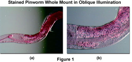
Uneven backgrounds are usually the result of employing off-axis lighting techniques, such as oblique and darkfield illumination, where the microscope illumination head is positioned at an angle with respect to the microscope optical axis. For example, in oblique illumination, even without a specimen in place on the stage, the viewfield reveals a gradient in light intensity that traverses the field from one edge to the other (see Figure 1). The magnitude of this effect is dependent upon the magnification zoom ratio, but usually appears with one side of the viewfield being much lighter than the opposite side.
Presented in Figure 1 are typical specimen viewfields observed in oblique illumination at low (Figure 1(a)) and high (Figure 1(b)) magnifications. The specimen is a stained pinworm (Enterobius vermicularis) prepared as a whole mount embedded in balsam medium. An extreme gradient, with a clearly defined boundary in the center, is evident in the low magnification image (Figure 1(a)) and is difficult to remove by simple adjustment of the illuminator. In contrast, the gradient becomes much smoother at higher magnifications (Figure 1(b)), and can be almost eliminated by carefully positioning the illumination head.
In cases where shallow to moderate background intensity (or brightness) gradients are present in digital images, they can often be eliminated by judicious application of the Olympus Background Subtraction Toolkit. After the software has been installed on the host computer (it is recommended that the software be located on the same computer that hosts the microscope software and hardware), the executable program can be accessed through the Windows Start button located in the lower left-hand corner of the toolbar. Clicking on this button launches a menu that contains a Programs selection, which leads to the toolkit software. Navigate to the menu item that contains the background subtraction software, and click on the listing to launch the program.
After initialization, the program presents the operator with a standard Windows dialog box entitled Please choose an image file to open. The default directory for file search is the root directory of the background subtraction software, which is usually not the preferred location for image files. Use the pull-down menu and/or navigational buttons located at the top of the dialog box to select a destination directory that contains the appropriate image files. Next, select a file and click on the Open button to load the image into the background subtraction application software. Note that the software is only capable of loading, processing, and saving images in one of the following formats: PSD (Photoshop Document), JPG (Joint Photographic Experts Group), BMP (Windows Bitmap), PCX (PC Paintbrush), TGA (Targa Image File), PNG (Portable Network Graphics), and PICT (Macintosh Graphics Files).

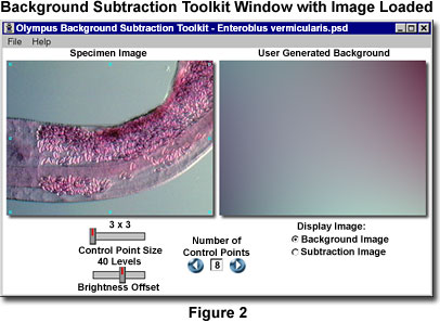
Once the background subtraction program has been launched, a window similar to that illustrated in Figure 2 appears on the screen. The title bar lists the program name (Olympus Expressions Background Subtraction Toolkit) and the name of the image that has been loaded into the software (E. vermicularis.psd in Figure 2). Appearing in the software window are two images entitled Specimen Image (on the left) and User-Generated Background (on the right). Each image appears in the window at a maximum size of 320 × 240 pixels by default, regardless of how large the original image is, unless the image size is smaller than the default value. In cases where the original image dimensions are less than 320 × 240 pixels, the image appears at its actual size and the software window is resized to match the image. The smallest window size is 350 × 190, which is the minimum space able to accommodate the application control sliders and radio buttons (the maximum window size is 672 × 430 pixels).
When the target image is loaded into the software window, 8 control points appear superimposed on top of the image with three positioned along the left-hand edge, three along the right-hand edge, one in the upper center, and one in the lower center. The Control Point Size slider can be utilized to adjust the number of pixels in each control box, ranging from 9 (3 × 3) to 81 (9 × 9), with intermediate values of 25 (5 × 5) and 49 (7 × 7). Increasing the number of pixels in the control points can often result in backgrounds that display a more even appearance.
The number of control points utilized in the background intensity calculations is regulated by clicking on the blue arrow buttons adjacent to the Number of Control Points text input box. After the 8 initial control points, new points are added on top of one another in the center of the image. They can be relocated by dragging anywhere within the image window. The minimum number of control points utilized by the software to calculate a background is 6, and lower numbers cannot be entered into the text input box. To manually type in a number of control points, click inside the text input box, type in the desired number, and click on one of the blue arrows or depress the Enter key. The maximum number of control points is 16, and background calculations can be performed with any number of control points between 6 and 16, inclusive.
Background Subtraction
Examine how a background subtraction image can be created from a digital image captured in the microscope with this interactive tutorial. Background regions used in the calculations can be selected with control points to generate a wide spectrum of possibilities.
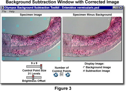
Performing background subtraction on images using the Background Subtraction Toolkit is functionally similar to the interactive Java tutorial, linked in the box above. A suitable background image can be constructed by dragging and dropping the square control points to appropriate locations inside the Specimen Image. A majority of the control points that lie on a neutral portion of the background appear cyan in color. Control points that are positioned on a lighter background region appear black in color, while those that fall on a darker background region appear white in color.
One or more of the control points may initially be superimposed over the specimen itself when the application program initializes. These points should be relocated to a background region to avoid introducing artifacts during creation of the background image. The control points should be distributed over the background to include as many of the intensity values as possible. For specimens that have severe background intensity fluctuations, more control points should be added using smaller areas (3 × 3 or 5 × 5). A typical specimen with properly distributed control points is presented in Figure 3, along with the resulting image after background subtraction. The image illustrated in Figure 3 features a stained pinworm whole mount (see Figures 1 and 2), which was captured in oblique illumination using an optical microscope. The best subtraction images result when control points are positioned so that the generated background image closely mimics that of the original specimen.

After the control point positions have been established, the calculated background appears in the User-Generated Background window, which has the same pixel dimensions as the Specimen Image window. To apply the background subtraction algorithm, click on the Subtraction Image radio button to subtract the newly calculated background image from the specimen image. The results will appear in the background window, which is now re-entitled Specimen Minus Background. Background subtraction may affect overall image brightness, by either reducing or increasing the brightness level of the entire image. The final step, therefore, is to adjust the Brightness Offset slider to restore the image to the correct value. This slider has an offset range of 0 to 70 levels.
After the specimen brightness has been adjusted, the image can be saved by using the File menu and selecting the Save option. When this feature is activated, a standard Windows Save As dialog box appears that enables the operator to navigate to the desired directory and to choose an appropriate file name for the processed image. Images will be stored at the same pixel size as the original, regardless of the size utilized in the background subtraction window display.
In transmitted light microscopy, the effects of nonuniformity in detector sensitivity and/or field illumination are often observed at very high magnification. Mottle, dirt, and a brightness gradient commonly appear in the image background, and these defects can seriously impair image contrast and mask important specimen detail. The removal of illumination defects and artifacts from images of highly magnified specimens is especially critical in video-enhanced contrast (VEC) microscopy. A method of background subtraction that is often employed in video microscopy involves capturing a background image by defocusing or by removing the specimen from the field of view. The captured background image is then repeatedly subtracted from each image that contains the specimen. This technique is not explored in the tutorial.
When it is not feasible to capture a background image in the microscope, a background image can be created artificially by fitting a surface function to the background of the captured specimen image. This artificial background image can then be subtracted from the specimen image. By selecting a number of points in the image that are located in the background, a list of brightness values at various positions can be obtained. The resulting information can then be utilized to obtain a least squares fit of a surface function that approximates the background. In the tutorial, eight adjustable control points are used to obtain a least squares fit of the background image with a surface function B(x, y) of the form:
where c(0) ... c(5) are the least squares solutions, and (x, y) represents the coordinates of a pixel in the fitted background image. The control points should be chosen so that they are evenly distributed across the image, and the brightness level at each control point should be representative of the background intensity. Placing many points within a small region of the image, while very few, or none, are distributed into surrounding regions will result in a poorly constructed background image. In general, background subtraction is utilized as an initial step in improving image quality, although (in practice) additional image enhancement techniques must often be applied to the subtraction image in order to obtain a useful result.
The polynomial fitting methods explored in this tutorial can be combined with automatic histogram analysis of regions throughout the image to locate the brightest or darkest points for fitting. Alternative methods of background subtraction rely upon grayscale morphology (primarily erosion) operations to remove narrow (bright or dark) features and yield a background suitable for removal. Note that subtraction of the background from a digital image captured in the microscope is often not an appropriate processing step. Background subtraction is the method of choice for logarithmic detectors (such as analog video cameras and film), but not for linear detectors (many digital cameras and flatbed scanners), where the proper technique is to divide the image by the background.