Photomicrography, like any form of photography, is prone to a variety of faults and errors regardless of the sophistication of the microscope equipment or the experience level and skill of the photomicrographer. Errors must be carefully examined to identify the source, which is usually due to either equipment failure, poor specimen preparation, improper technique, or processing mistakes.
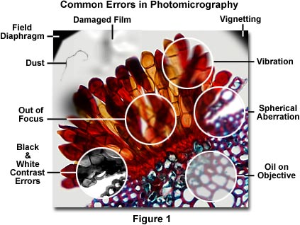
A majority of photomicrography errors can be traced to the optical configuration of the microscope, including improperly adjusted illumination, use of the wrong filters, or incorrect setting of the condenser and/or field aperture diaphragms. The next most common problems arise because of poor specimen preparation and dirt, dust, or contaminating oils on the specimen or microscope optics. Figure 1 presents a photomicrograph of a wheat rust pustule (caused by an infection by the fungus Puccinia graminis) illustrating several common photomicrography errors. The central portion of this figure (enclosed in a white circle) is out of focus, and the upper left and right-hand corners exhibit shadows from the field diaphragm and vignetting. Contrast errors in photomicrography using black & white films are represented in the lower left-hand portion of Figure 1 as an area showing poor choice of contrast filters that has resulted in too much image contrast in the photomicrograph. Focus problems and lack of specimen detail and contrast due to vibration, spherical aberration, and contaminating oil on the objective front lens are illustrated within white circles on the right-hand side of Figure 1. Also included in the photomicrograph is a film damage error and dust contamination. These and other similar errors, such as the use of specimens that are too heavily stained or too thick, represent the most frequent errors that confront a microscopist during routine photomicrography. The following paragraphs address specific errors and faults in photomicrography and present suggested remedies.
Image Out of Focus, Hazy or Unsharp - A lack of proper focus and/or blurry images represent one of the most common errors in photomicrography. The source of these errors is usually the result of vibration in the microscope stand or improper adjustment of the focal distance between the optics and the film plane. Often, the image will appear in sharp focus through the eyepieces, but resulting photomicrographs are blurred or unsharp (Figure 2(a)). This is an indication that the film plane and viewing optics may not be parfocal. In microscopes equipped with a focusing telescope, check the cross hairs in the reticle to ensure they are in sharp focus. Carefully adjust the focus between the eyepiece reticle (if so equipped) and the focusing telescope so that both reticles are simultaneously in focus. If the eyepiece reveals a specimen that is in focus, but the reticle in the photo eyepiece is not focused, then the specimen image will appear unsharp on film and visa versa. Use our interactive Java tutorial on Photomask reticle Operation to practice this technique.
Photomask Reticle Operation
Practice adjustment of the photomask reticle mounted in a focusing eyepiece using this interactive Java tutorial.
Parfocal errors often occur with low power (1x -4x) objectives where the film plane depth of focus is very shallow and a slight mis-adjustment of the microscope focus knob results in unsharp images (see Figure 2(a)). The reticles in both the eyepieces and focusing telescope should be in sharp focus, and the interpupillary distance between oculars should be properly maintained. Use a low magnification objective (10x) to carefully focus the specimen through the eyepieces using a stage micrometer or specimen with sharp edge definition. Next, adjust the reticle in the focusing telescope until the image is in sharp focus, making sure the thin cross hairs in this reticle are also focused and distinct when superimposed over the aerial image. Many manufacturers offer an aftermarket focusing aid, which is a simple adjustable magnifier that can be used to view the focusing telescope reticle to aid in focus adjustments. Adjust both eyepieces so they are parfocal with each other and the focusing telescope. Also check the projection lens or phototube eyepiece to ensure it is firmly seated.
When using a standard SLR camera back for photomicrography, the image must be focused through the camera focus finder, which is usually a ground-glass screen. At low magnifications, the screen does not present a problem, but if the surface of the ground glass is too coarse, focusing can become difficult at higher magnifications. If this problem occurs, switch to a focusing screen with a clear center for critical focus of the image, or modify the focusing screen of large format cameras by cementing a small coverslip to the ground glass screen surface (as suggested by John Delly in his book "Photography Through the Microscope") using Canada balsam as an adhesive. The resulting combination with provide a transparent center in the area of the screen overlaid by the coverslip. Delly also suggests using a soft pencil or India ink to draw a cross or two diagonals on the ground glass surface prior to cementing on the coverslip. This procedure provides a set of "cross hairs" for parallax focusing.
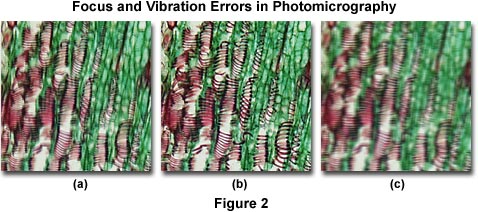
Presented in Figure 2 are several photomicrographs that illustrate errors in microscope focus (Figure 2(a)) and unsharp images due to vibration (Figure 2(c)). The specimen is a thin section of Tilia (Basswood) stem stained with a quadruple mixture designed specifically for plant tissue. Figure 2(a) depicts a typical photomicrograph that is not in focus due to improper adjustment of the focal distance between the optics and the film plane, caused by errors discussed above. On the right (Figure 2(c)) is a photomicrograph of the same viewfield, but affected by severe vibration that has resulted in loss of image sharpness. The photomicrograph in Figure 2(b) illustrates the Tilia stained thin section in sharp focus.
Microscopists who are astigmatic and must wear glasses can experience difficulty in producing sharp images even though the specimen appears in focus through the eyepieces. It is often especially difficult to adjust specimen focus through a focusing telescope while wearing eyeglasses. The cure is to use a set of high-eyepoint eyepieces or focusing telescope to correct the problem. Check with the microscope manufacturer to make certain these accessories are available.
Focus can also be a problem when the specimen preparation is too thick or when the microscope slide is inadvertently examined upside down (Figure 3(a)). Thickness errors can often be overcome by using long working distance objectives, but the best solution is to remake the specimen using thinner sections or to squeeze the coverslip more tightly over the preparation. The simple fix for an upside down microscope slide is to flip it over so the cover glass is facing the objective (Figures 3(a) and 3(b)). Occasionally, several coverslips will stick together during specimen preparation and the resulting microscope slide will have two or more coverslips, causing spherical aberration problems in resulting photomicrographs. If this error is suspected, carefully examine the microscope slide containing the coverslips for the presence of interference fringes, which will occur because of the residual space between the two coverslips. Force the uppermost coverslip off using a pair of tweezers.
Incorrect adjustment of the correction collar on high magnification dry objectives or the use of high dry objectives having high numerical apertures with a mismatched cover glass (coverslip) is often a cause of unsharp photomicrographs (Figure 3(c)). These errors are caused by under or overcorrection for spherical aberration when microscope coverslips are either too thick or too thin. In this case, it will be impossible to accurately focus the microscope and obtain a sharp image. The solution to coverslip thickness problems is to replace an unsuitable coverslip with one of the correct thickness (usually a No. 1½ cover glass, which averages 0.17 millimeters thick with a standard variation between 0.16 and 0.19 millimeters) or to use an objective equipped with a correction collar that can be adjusted to match coverslip thickness. If the coverslip thickness cannot be adjusted (i.e., it is glued onto the specimen slide) or if the thickness is unknown and an objective with a correction collar is not available, then the problem can sometimes be remedied by using an oil immersion objective of comparable magnification. Because the refractive index of immersion oil is very similar to that of the coverslip, thickness variations become less important.
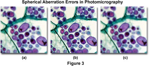
Photomicrographs illustrated in Figure 3 show the effects of spherical aberration errors. The specimen is a stained thin section of potato (Solanum tuberosum) tissue infected with blight fungus. Figure 3(a) shows the effects of an inverted (upside down) microscope slide, which results in a loss of contrast and sharpness in the image due to spherical aberration. Likewise, Figure 3(c) illustrates incorrect adjustment of the correction collar on a high numerical aperture and high magnification objective. The coverslip thickness for this specimen is 0.17 millimeters, but the correction collar was adjusted for a thickness of 0.23 millimeters. Figure 3(b) shows how the photomicrograph should appear when the coverslip thickness is optimized and the microscope is properly adjusted.
Another cause of unsharp images is oil (either immersion oil or natural oils derived from fingerprints) on the objective front lens, the top lens of the photo eyepiece (projection lens), or the specimen slide. Oil present on the front lens of a dry objective is a common accident that can occur when the objective is placed in position over a previously oiled slide. If a stereoscopic microscope is available, remove the objective and/or photo eyepiece and examine it carefully at high magnification. Oil contamination can often be seen on the front lens using this technique. Removal of oil from a microscope lens can be difficult and often leads to replacing old dust present on the lens with new dust and debris. Clean the lens by first gently removing excess oil from the surface with lens tissue, then use a wooden applicator with surgical cotton or high quality lens paper to wipe the lens clean after moistening it with trichloroethane, ether, or xylol. Avoid the use of too much solvent, which can attack cement used to secure the lens to its mount.
After removal of contaminating oil, use a camel hair or sable brush to remove any dust, dirt, or debris that may be present on the lens. The brush can be degreased by dipping it into a small volume of ether and shaking it dry. An air balloon or rubber ear syringe is often useful for blowing off loose dust from the lens, but do not use canned air, because it can leave a residue that is more difficult to remove than immersion oil. Contaminating immersion oil occurs most often on objectives designed for use with immersion media, but dry objectives can also become contaminated when they are swung over the top of a coverslip having residual oil from observation using an immersion objective. Always check the front lens of dry objectives for contamination when experiencing focus errors or unsharp images with these objectives.
In many older microscopes, objectives were specifically matched to eyepieces in order to correct for optical aberration in the final image. Unsharp images can also be caused by a mismatch of tube length mechanical dimensions between the microscope body tube and the objective. Most objectives used in fixed tube length microscopes are designed for a tube length of 160 millimeters, but this is not invariant and using an objective with a mismatched tube length will lead to the introduction of spherical aberration, reducing image sharpness. Tube length requirements are usually inscribed on the objective barrel, so check this value to ensure an objective is compatible with the microscope before use. Objectives with infinity optical correction are intended for use in microscopes equipped with a tube lens, and are not suitable for use in older standard fixed tube length microscopes. Likewise, objectives designed for a fixed tube length microscope should not be used with infinity corrected microscopes.
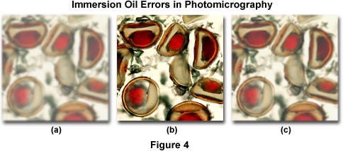
Figure 4 illustrates several errors that commonly occur when using immersion oil. The specimen is a multiply stained thin section of alfalfa plant tissue that has been infected with the crown wart fungus, Physoderma alfalfae. The photomicrograph on the left (Figure 4(a)) demonstrates the image formed by a high magnification (60x) oil immersion objective when an air bubble has been trapped between the microscope coverslip and the objective front lens. Under these conditions, the resulting image is hazy and unsharp and suffers from a dramatic loss of contrast. If the eyepiece is removed, the oil bubble can be clearly seen at the rear focal plane of the objective. This error usually occurs when an oil objective, which usually have a slightly concave front lens, is lowered into a pool of oil that has been placed on the top surface of a coverslip. Objectives should never be lowered into immersion oil. Instead, the best practice is to "swing" the objective into place above the oil with a swiping action by rotating the nosepiece to avoid trapping of air between the coverslip and the objective front lens. Figure 4(c) illustrates a photomicrograph taken under similar conditions, but with a dry 60x objective. The resulting image is in better focus and has significantly more contrast than the one displayed by Figure 4(a). In this case, image deterioration is due to contamination by oil on the objective front lens. Dry objectives placed adjacent to oil immersion objectives in the microscope nosepiece can easily be contaminated with oil when the objective is accidentally swung through a pool of oil on the microscope coverslip. The image in Figure 4(b) is free from errors and represents the infected alfalfa tissue as it should appear.
Intermittent focus errors often occur due to vibration, and usually are seen when high magnification objectives are used for long exposure times. Test for vibration problems by focusing the microscope on a sharp specimen using the highest magnification objective available. Continuous vibrations usually cause the specimen to appear in motion. Vibrations from the table or wind currents from air-handling units and fans will cause the microscope to slowly lose focus. Allow the microscope to remain stationary while focused on the specimen and measure the time required for vibrations to bring the microscope out of focus. If focus drop occurs immediately, some form of vibration isolation is necessary. However, if the microscope will stay in focus at high magnification for several minutes or longer, then vibration is sufficiently low enough to have an insignificant influence on most photomicrography.
The effects of continuous vibration errors can be partially overcome by using very fast shutter speeds, usually on the order of one or several hundredths of a second. Electronic flash units can also be used to increase illumination with faster shutter speeds to overcome vibration errors in photomicrography. However, this remedy only minimizes the effect of vibration artifacts and will not eliminate the cause. In cases where vibration problems are significant, the microscope should be mounted on a suitable set of shock absorbers for vibration isolation. Several of the microscope manufacturers and some aftermarket suppliers offer vibration "pads" (usually made of Neoprene, silicone, or a similar polymer) that can be placed under the microscope foot pads.
Stage drift is a problem that occurs when the weight of the stage induces movement in the microscope focus rack, lowering the stage (and specimen) and causing the microscope to lose focus. In many modern microscopes, a focus rack tensioning mechanism is included to eliminate or reduce drift. Older microscopes that experience this problem may have a worn or loose focus rack and should be serviced by a professional repair technician.
Some vibration problems are caused by mechanical shutter actions in camera attachments. Always use a cable release with cameras having a mechanical shutter and increase exposure time to exceed one second with neutral density filters if vibration problems persist. The longer exposure times will minimize the effect of shutter vibration, which only occurs during the initial part of the exposure.
Contrast Errors and Poor Image Resolution - Poor contrast is usually an indication that the substage condenser aperture diaphragm is opened too wide, causing flare and considerably reducing image contrast. This problem plagues all types of photomicrography, including color, black & white, and digital. To correct the problem, remove one of the eyepieces and insert a phase telescope into the eye tube or (if the microscope is so equipped) swing a Bertrand lens into the light path. While observing the rear focal plane of the objective, adjust the condenser aperture diaphragm until its diameter lies between 65 and 80 percent of the objective aperture (to achieve proper Köhler illumination and maximize image contrast). When using a reflected light microscope, adjust both the field diaphragm and the aperture diaphragm to improve contrast.
As mentioned above, utilizing a high numerical aperture objective with a coverslip that has an incorrect thickness can also result in a loss of contrast (and lack of image sharpness) due to spherical aberration. Check the objective barrel to see if it matches the coverslip thickness, or switch to an objective with a coverslip thickness correction collar. Reflected light objectives are corrected for observation and photomicrography without the use of a coverslip, so avoid coverslips with objectives of this type.
The specimen itself may be the source of contrast problems. Transparent and unstained specimens are difficult to image using brightfield illumination and produce far better photomicrographs when using one of the contrast enhancing techniques such as phase contrast, Hoffman modulation contrast, or differential interference contrast. Oblique illumination will also improve contrast in unstained specimens.
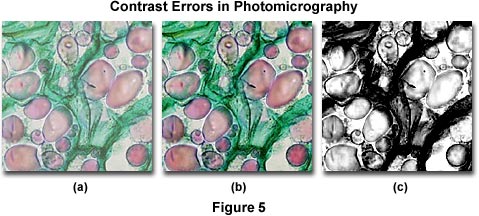
When using contrast filters in black & white photomicrography, poor filter choices can often lead to lack of specimen contrast in resulting photomicrographs. Proper use of contrast filters will ensure better rendition of specimen detail when using stained specimens, but only if the color of the filter is complementary to that of the specimen. When light of the same color as the stained specimen is transmitted through the specimen, the result is reduced contrast between the specimen and the background. Optimum results are obtained when using filters that have minimal or only partial absorption in the regions where the specimen absorbs visible light. Contrast can also be improved in black & white photomicrography by the use of high contrast film (such as Kodak Technical Pan) or through the use of chemical developers that produce high contrast.
Several contrast errors in photomicrography are presented in Figure 5, which illustrates a series of brightfield images of a multiply-stained potato (Solanum tuberosum) tissue thin section. The photomicrograph on the left (Figure 5(a)) was taken with Fujichrome 64T, a tungsten-balanced transparency film that usually displays a significant amount of contrast when properly processed. In this case, the image is lacking in contrast due to improper processing and/or the condenser aperture diaphragm being opened too wide. Figure 5(c) illustrates a black & white photomicrograph taken of the same field, but using contrast filters and processed with a high-contrast developer. The excessive amount of contrast in Figure 5(c) is due to incorrect choice of color filters used to increase contrast in black & white photomicrography. Instead of using a filter that has partial absorption in the green region of the visible spectrum (to bring out contrast in the red vesicules), a Kodak Wratten number 25 red filter was chosen for the exposure and the film was then erroneously processed in a developer under conditions that generated excessive contrast. The center photomicrograph (Figure 5(b)) illustrates the potato thin section as it should appear.
Contrast in Black & White Photomicrography
Explore the use of Kodak Wratten color filters for contrast control in black & white photomicrography when using stained specimens.
Poor contrast can also occur when imaging specimen preparations that are too thick, as discussed in detail above. This situation can be overcome by careful specimen preparation, using thinner specimens with the coverslip positioned firmly in place and secured with a transparent adhesive such as Canada balsam.
Although less of a problem with color films, too much contrast is a common occurrence in black & white photomicrography. The primary cause, as discussed above, is incorrect choice of contrast filters with stained specimens, but film processing errors should also be suspect. When using a high-contrast film such as Kodak Technical Pan, the choice of film developer should coincide with the filter combination used to capture the image. If contrast filters designed to reduce specimen contrast are chosen, then the developer should also produce low-contrast images on black & white negatives. Conversely, when using contrast filters to improve specimen contrast, choose a high-contrast developer to assist in producing the correct amount of contrast in the final images. Use of a high-contrast developer with normal film can often lead to images having too much contrast, as will a prolonged development time. Because of the wide latitude of choices in films and developing agents for black & white film, careful attention should be paid the development process in order to fine-tune contrast in resulting photomicrographs.
Poor resolution in photomicrography is often the result of improper adjustment of the substage condenser aperture diaphragm. When a microscope is properly configured for Köhler illumination, the aperture diaphragm should have an iris diameter opening that lies between 65 and 80 percent of the objective aperture. If the diaphragm is opened too far, poor image contrast will result (Figure 6(a)) and the photomicrograph will suffer from loss of visibility. If the diaphragm opening is reduced to a diameter that is less than 50 percent of the objective aperture, resolution is significantly reduced and diffraction artifacts become noticeable in photomicrographs. When the aperture diaphragm opening is reduced to its smallest size, severe image deterioration occurs and photomicrographs become dark and obscured with diffraction artifacts, predominantly dark halos surrounding the edges of fine structural details. A similar situation occurs when the substage condenser is positioned too low beneath the microscope stage. Both of these errors are the result of a reduction in the size and quality of the illumination cone produced by the condenser, which does not allow the objective to operate at its full numerical aperture.
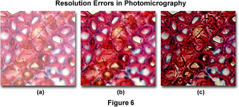
Common resolution errors in photomicrography are presented in Figure 6, which illustrates a series of photomicrographs of a plum tree stem tissue stained thin section infected with Black Knot, a destructive disease of plum trees caused by the fungus Apiosporina morbosa (also known as Dibotryon morbosum). The plum tree tissue section is selectively color stained to reveal fine detail and differentiate between sub-cellular components for observation. In this figure, the effects of condenser aperture diaphragm opening settings on the quality of images captured by photomicrography are displayed using Fujichrome 64T transparency film with a 40x planachromat objective (NA = 0.75) and a swing-out top lens achromatic condenser (NA = 0.90). The approximate condenser aperture opening sizes are: Figure 6(a) - 95 percent (NA = 0.81); Figure 6(b) - 60 percent (NA = 0.54); and, Figure 6(c) - 20 percent (NA = 0.18).
In Figure 6(a), where the aperture diaphragm is set to a position in which the numerical aperture of the condenser and objective are nearly equal, much of the fine specimen detail is visible, although there remains a considerable amount of scattering and glare and overall image contrast is heavily compromised. The image is also significantly brighter than its counterparts, which were made with a smaller setting of the aperture diaphragm. Figure 6(b) illustrates the plum stem at a condenser aperture size that produces a numerical aperture approximately 70 percent that of the objective. Glare is reduced, the image is very sharp, and fine image detail is present without significant diffraction artifacts. For this specimen, the photomicrograph in Figure 6(b) represents the optimum setting for the condenser aperture diaphragm. When the diaphragm is closed to the smallest setting at about 25 percent of the objective numerical aperture (Figure 6(c)), fine image details become obscured with diffraction artifacts. The image also takes on a darker overall cast that produces shifts in the color hues of the specimen. This concept can be explored in greater detail using the interactive Java tutorial on the substage condenser aperture diaphragm.
Condenser Effects on Image Contrast
Discover how the size of the condenser aperture affects specimen image contrast.
From the above discussion it is evident that the condenser aperture diaphragm should be set to a position that will provide a compromise mixture of direct and deviated light that depends, to a large degree, on the absorption, diffraction, and refraction characteristics of the specimen. This must be accomplished without overwhelming the image with artifacts that obscure detail and present erroneous enhancement of contrast. The amount of image detail and contrast necessary to produce the best photomicrograph is also dependent upon refractive index, optical characteristics and other specimen-dependent parameters. When using contrast enhancing techniques, proper alignment and configuration of the microscope is important to ensure accurate rendition of specimen detail under these specialized conditions.
When the aperture diaphragm is erroneously closed too far, deviated light begins to obscure direct illuminating rays, resulting in diffraction artifacts that cause visible fringes, banding, and/or pattern formation in photomicrographs. Other problems, such as refraction phenomena, can also produce apparent structures in an image that are not real. Alternatively, opening the condenser aperture too wide causes unwanted glare and light scattering from the specimen and optical surfaces within the microscope. This leads to a significant loss of contrast and washing out of image detail. The correct setting will vary from specimen to specimen, and the experienced microscopist will soon learn to accurately adjust the condenser aperture diaphragm (and numerical aperture of the system) by observing the image without having to view the diaphragm in the back focal plane of the objective. In fact, many microscopists believe that critical reduction of the numerical aperture of the microscope system to optimize image quality is the single most important step in photomicrography.
Illumination Errors - Establishing the conditions for proper Köhler illumination is perhaps the most important aspect of microscope configuration for critical photomicrography. Illumination errors occur most frequently when the light source is not correctly positioned and/or the objective and substage condenser are not aligned with respect to each other or on center with the microscope optical axis. A slight mis-alignment of these components may not be noticeable while viewing a specimen through the eyepieces, but the error will yield an intensity gradient in resulting photomicrographs. The result will be a photomicrograph that displays uneven illumination with one side of the specimen image or background being darker than the other.
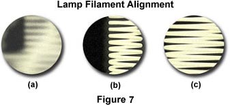
When photomicrographs show evidence of illumination errors, first check the lamp filament alignment, the lamphouse reflector position, and the diffusion screen that is positioned between the lamphouse and the microscope base. A missing diffusion screen will result in the image of the lamp filament being projected into the specimen image conjugate plane and may cause bright spots, dark spots, and uneven illumination in photomicrographs. If the diffusion screen is properly positioned, examine the lamp filament alignment (remember to remove the diffusion screen from the optical pathway before attempting to check filament alignment). Many current microscopes feature pre-centered halogen lamps and built-in diffusion filters. For these instruments, centration of the lamp filament has already been achieved during assembly by the manufacturer. Figure 7 illustrates a typical view of the microscope light port when the filament is made visible by placing a sheet of white paper, frosted glass, Kimwipe, or lens-cleaning tissue on the microscope port. The port on the left in Figure 7(a) contains a filament that is severely out of alignment and not positioned properly to focus an image that will completely fill the aperture diaphragm nor the back focal plane of the objective. Using translational adjustments on the lamp housing, the filament is brought into focus (Figure 7(b)) and then centered within the light port (Figure 7(c)).
Difficulty in properly aligning the filament can arise if the collector lens is not correctly focused. Most microscopes with built-in illuminators lack an adjustment for the collector lens, which is pre-aligned and focused at the factory. In this case, the microscope must be serviced by a trained technician. Older microscopes may have an adjustment for the collector lens, or may be equipped with external illuminators that have a variety of adjustments. After the lamp filament has been correctly aligned, replace the diffusion screen in its position between the lamphouse and the microscope base. Note that in older microscopes equipped with tungsten bulbs, the position of the filament within the bulb may vary from one lamp to another. Before resuming photomicrography, examine the microscope illumination through the widest possible field by viewing through the eyepieces with no specimen present. This is accomplished by selecting the lowest power objective available and placing a neutral density filter in the light path to reduce illumination intensity. If the field of view still appears to have uneven illumination, then alignment of the substage condenser is suspect.
Lamp Filament Alignment
Use this tutorial to practice lamp filament alignment while monitoring the filament both in the microscope port and at the back focal plane of the objective.
The substage condenser is usually equipped with a pair of centering screws that allow the microscopist to center the condenser with respect to the objective and the optical axis of the microscope. This procedure is necessary to establish Köhler illumination, but the condenser can become mis-aligned during routine use of the microscope. To check the condenser position, first rotate the 10x objective into position with a lightly stained specimen in place on the microscope stage. Next, focus the field diaphragm by raising or lowering the substage condenser using the rack mechanism located beneath the stage. The diaphragm should be superimposed over the focused image of the specimen and the aperture closed until the individual blades appear in sharp focus with the iris opening diameter filling approximately 25-40 percent of the viewfield. Use the centering screws located on the condenser housing to center the field diaphragm opening in the viewfield and open the blades until they are just outside the field of view. If the field diaphragm blades obscure too much of the viewfield, they can be a source of uneven illumination.
Objectives mounted in a rotating turret rarely are the source of alignment errors because they are secured into position with a détente. Some polarizing microscopes have a specialized nosepiece that allows the objectives to be centered in the optical pathway by means of a pair of centering screws. These objectives are particularly useful when coupled to a pre-centered circular stage that rotates through a 360-degree angle (older microscopes equipped with a circular stage often require centering of the individual objectives). A birefringent specimen can be placed on the stage and used to assist centering the objectives in the optical pathway. To avoid problems with mis-aligned objectives, always check to ensure the nosepiece is positioned solidly within the range of the détente index stop. When rotated, the nosepiece should "click" into the same position in the optical pathway for each objective.
Gradual darkening at the outside edges of the image (commonly referred to as vignetting) in photomicrographs is usually caused by either an incorrectly aligned substage condenser, or the condenser is not set to the proper height beneath the microscope stage. When the condenser is not configured correctly, reducing the size of the opening in the aperture diaphragm can resulting in darkening at the periphery of the field, or vignetting in photomicrographs (Figure 8(c)). Another cause of vignetting is use of a photo eyepiece having a magnification factor that is incompatible with the film emulsion size and unable to fill the full film diagonal, or having a trinocular photo tube of lesser or greater length than is necessary to project the image on the film plane. As an example, the diagonal of a 4 × 5-inch photomicrograph is 145 millimeters. When using a projection lens with a 0.63x magnification factor (commonly used with digital CCD cameras), an 10x eyepiece having a field size of 21 millimeters will produce an image 132 millimeters in diameter, resulting in vignetting at the corners of the image. Changing to a 1x or (more commonly) 2.5x projection lens produces field sizes of 210 and 525 millimeters, respectively. The higher magnification projection lenses will produce images that are free of vignetting.
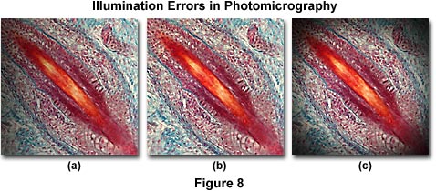
The photomicrographs illustrated in Figure 8 feature a stained thin section of fetal pig tooth. Figure 8(a) shows the tooth thin section when the lamp filament is not correctly centered. In this case, there is a gradual darkening of the image from right to left in the photomicrograph. Vignetting of the image is illustrated in Figure 8(c), which is manifested in a gradual darkening at the edge of the image area that encompasses a circular pattern surrounding the image as a result of incorrect substage condenser height. This error also occurs when the camera shutter speed is too fast to allow the film to respond (shutter speeds faster than 0.01 second). The photomicrograph in Figure 8(b) shows how the image should appear when microscope illumination is configured properly.
When the corners of a photomicrograph reveal dark, sharply focused images of an iris diaphragm shutter blade, then the field diaphragm is probably not opened sufficiently and should be visible in the eyepieces. The proper adjustment of the field diaphragm iris opening size is just outside the field of view or at least outside the field area included in photomicrographs. Another error that results in similar photomicrographs (dark corners) can often occur when the camera shutter is positioned too far above the eyepoint. At fast shutter speeds, an image of the camera shutter blades can be recorded as a silhouette image on the photomicrograph, an error known as shutter shadow. Although less common with modern microscopes that often have matched camera systems, shutter shadow can be a problem when attaching a camera having an integral lens system. In the latter case, the camera lens will dictate the eyepoint position. To alleviate the problem, place neutral density filters in the light path to increase exposure times, thus permitting slower shutter speeds.
Dark Spots and Debris - Dirt, dark spots, and debris on photomicrographs are common sources of problems with photomicrography, and may occur either in focus with the image or as a blurred spot on the film. Contamination of this type can appear as colored artifacts when using color film, and as black or gray spots on black & white film. If the debris appears in sharp focus, then it is usually occurring from contamination of a lens surface residing in a plane conjugate to the focused specimen. The field lens and any glass (often color balancing or correcting filters) adjacent to the microscope field diaphragm are often prone to collecting dirt, and these components lie near one of the principal image conjugate planes. Contamination near the field diaphragm will appear in sharp focus on film, and scratches or dirt on filters placed near the field diaphragm are often a source of haze and debris artifacts. Glass surfaces that have been scratched will appear as unsharp areas on photomicrographs, as will bubbles embedded in the lamp condenser glass or in heat-absorbing filters. Often these bubbles will have a bluish tinge when recorded on film. Contamination of the diffusion screen surface with dust and debris or imperfections within the glass of the screen (bubbles) result in pink or blue spots on photomicrographs.
Another common source of dirt and debris is the specimen itself, which also resides in a conjugate plane. Dust adhering to the surface of the coverslip will appear as unfocused dark spots on the film, while contamination underneath the coverslip near or mixed with the specimen will usually appear as debris that is in focus with the specimen. Dust and debris on a lens near the intermediate image plane is not common, but can sometimes occur. This plane is positioned at the fixed diaphragm of the eyepiece, which can become contaminated when the eyepiece is removed from the microscope and the lens nearest the fixed diaphragm becomes dirty.
When viewing contamination through the microscope eyepieces and attempting to locate the source, slowly turn each eyepiece individually to determine if the debris spots rotate with one of the eyepieces. If so, then the contamination resides on the eyepieces themselves. Rotate other components in the microcope optical pathway, such as filters, the projection lens, the camera system, and the condenser when trying to locate the source of dust and debris. In some instances, it is helpful to capture photomicrographs for the purposes of constructing a record as the components are being rotated. Also translate the specimen back and forth while observing through the eyepieces to determine if debris moves with the specimen. Finally, swing the objective and condenser top lens into and out of the light path and examine whether contaminating debris shifts with either the objective or condenser.
Occasionally, fibers and lint may become wedged between leaves in the field diaphragm or caught in the film carrier inside the camera or black box. When this occurs, the debris will appear in sharp focus (see Figure 9(c)). This type of contamination is more difficult to diagnose and may present some problems with removal. If there is debris in the field diaphragm, an experienced repair engineer should be employed for microscope cleaning. Debris in the camera back can be removed with compressed air or a camel hair brush. Cleaning dirt and debris from lenses, filters, and the specimen slide should be carefully done with lens tissue or a soft cotton swab. Remove any loose dirt using a can of compressed air held at a distance or by gently sweeping with a camel's hair brush.
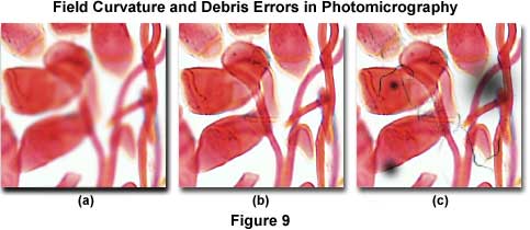
Figure 9 presents several photomicrographs that display dust and debris contamination errors in addition to field curvature errors. The specimen is a multiple-stained thin section of apple tree stem infected with cedar apple rust, a disease affecting apple trees in North America east of the Rocky Mountains. It is caused by the fungus Gymnosporangium juniperi-virginianae and can defoliate trees and blemish fruit making them unmarketable. The photomicrograph illustrated in Figure 9(c) shows the effects of heavy contamination by dust, debris, and out-of-focus dark spots on the image. These artifacts can arise from a number of reasons, and debris can be located in several areas on the microscope and/or specimen as discussed above. Image focus problems arising from field curvature aberrations plague the photomicrograph in Figure 9(a), which has sharp definition at the edges, but has lost focus in the center. These errors will be discussed subsequently.
Bright Spots and Specular Reflections - Bright spots on photomicrographs may arise from specular reflections from overhead lighting or auxiliary illumination from external light sources. These errors are particularly prevalent when making very long exposures in fluorescence photomicrography. To remedy this problem, either turn off overhead lights (or auxiliary illumination) or cover the area directly affected. On older microscopes a similar problem can occur when a beamsplitter is used between the viewing binocular head and the phototube. Circumvent the problem by adjusting the beamsplitter to a position where all microscope illumination is directed into the phototube. Reflections can also become a problem when specimens are imaged while bathed in solution or through a very thick cover glass and/or specimen holder (exceeding 1 millimeter) using long working distance objectives. There is no easy cure when imaging through thick glass, but reflections from the surface of aqueous solvent can be alleviated by using water immersion objectives.
Bright spots in photomicrographs can occur when a conventional SLR camera is used with an integral lens to capture images. Similar spots also are common with an eyepiece camera that has a reduction lens lying above the microscope projection lens. The front surface of the camera lens should be positioned as close to the eyepoint of the projection lens as possible to avoid bright spots. If it is too close, an image of the objective rear lens may be recorded as an out-of-focus spot on the film. The spot will appear bright on transparency film, or as a dark spot on color or black & white negative film. This problem can often be alleviated by repositioning the camera with respect to the photo eyepiece or projection lens. To avoid vignetting, be careful not to move the camera too far away from the projection lens.
Field Curvature Errors - When the edges of the photomicrograph are in sharp focus, but the center has lost its focus (Figure 9(a), the problem is probably curvature of field aberrations in the objective. Check the objective barrel to ensure it is marked plan, indicating the objective has been corrected optically for flatness of field. Uncorrected objectives will not produce a sharp image across the entire microscope viewfield. This error also occurs in reflected light specimens when the specimen is slightly tilted or mounted at an angle. To correct the problem, remount the specimen or use modeling clay and a compressor to provide an adjustable level base. Most objectives display a finite amount of field curvature aberration due to distance variations in the path of on-axis and off-axis image forming light waves. In this case, use the fine focus knob to drift through focus from the edges to the center, in order to confirm field curvature aberrations. Replace uncorrected objectives with plan objectives to solve the aberration problem. If objective replacement is impossible, limit the area recorded in the photomicrograph to the center of field whenever possible, or install a projection lens of higher magnification to reduce the field size.
Bands of Fog - When photomicrographs show banded areas that are fogged or washed out, then the problem is probably caused by opening the camera back very briefly in the light. This condition can also occur when the camera back has a light leak along the hinges or catch. The degree of fogging will depend upon the length of time the back was open and the brightness of room light. To alleviate this problem, make certain the film is completely rewound before opening the camera back. If a light leak is suspected, have a qualified service technician inspect the camera back.