The term lens is the common name given to a component of glass or transparent plastic material, usually circular in diameter, which has two primary surfaces that are ground and polished in a specific manner designed to produce either a convergence or divergence of light passing through the material. The optical microscope forms an image of a specimen placed on the stage by passing light from the illuminator through a series of glass lenses and focusing this light either into the eyepieces, on the film plane in a traditional camera system, or onto the surface of a digital image sensor.
The action of a simple lens, similar to many of those used in the microscope, is governed by the principles of refraction and reflection and can be understood with the aid of a few simple rules about the geometry involved in tracing light rays through the lens. The basic concepts explored in this discussion, which are derived from the science of Geometrical Optics, will lead to an understanding of the magnification process, the properties of real and virtual images, and lens aberrations or defects.
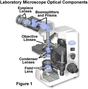
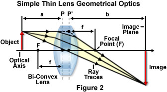
In order to understand the optical system of a simple microscope (locations of the lens elements in a common laboratory microscope are presented in Figure 1), the basic properties of a simple thin lens having two light-refracting surfaces and a central optical axis must first be described. Each lens has two principal planes and two focal planes that are defined by the geometry of the lens and the relationship between the lens and the focused image. Light rays passing through the lens will intersect and are physically united at the focal plane (see Figure 2), while extensions of the rays entering the lens will intersect at the principal plane with extensions of the rays emerging from the lens. The focal length of a lens is defined as the distance between the principal plane and the focal plane, and every lens has a set of these planes on each side (front and rear).
Traces of light rays passing through a simple bi-convex thin glass lens are presented in Figure 2, along with the other important geometric parameters necessary in forming a focused image by the rays. The focal points of the lens are denoted by the variable F, and there are two separate focal points, one in front of the lens (on the left-hand side of Figure 2) and one behind the lens (on the right). The principal planes of the lens (P and P' in Figure 2) are denoted by dashed lines, and the distance between each principal plane and its respective focal point represents the focal length (f). Because the bi-convex lens illustrated in Figure 2 is symmetrical, the principal planes are located equal distances from the lens surfaces, and the front and rear focal lengths are also equal.
Simple Bi-Convex Thin Lenses
Explore how changes to focal length and object size affect the size and position of the image formed by a simple bi-convex thin lens. Ray traces and focal points are shifted as lens and object parameters are varied in this interactive tutorial.
The object (or specimen) being imaged by the lens is positioned in the object plane, located on the left-hand side of the lens by convention, and is represented by a red arrow that travels upward from the centerline or optical axis, which passes through the center of the lens, perpendicular to the principal planes. Ray traces through the lens (yellow arrows) emanate from the object and proceed from left to right through the lens to form a magnified real image (inverted red arrow) in the image plane on the right-hand side of the lens. The distance between the front principal plane of the lens and the specimen is known as the object distance, and is represented by the variable a in Figure 2. In a similar manner, the distance from the rear principal plane to the image (the variable b in Figure 2) is termed the image distance. These parameters are the fundamental elements defining the geometrical optics of a simple lens and can be used to calculate important properties of the lens, including focal length and magnification factor.
Lenses can be either positive or negative depending upon whether they cause light rays passing through to converge into a single focal point, or diverge outward from the optical axis and into space. Positive lenses (illustrated in Figures 2 and 3) converge incident light rays that are parallel to the optical axis and focus them at the focal plane to form a real image. As shown in Figure 3, positive lenses have one or two convex surfaces and are thicker in the center than at the edges. A common characteristic of positive lenses is that they magnify objects when they are placed between the object and the human eye. In contrast, negative lenses diverge parallel incident light rays and form a virtual image by extending traces of the light rays passing through the lens to a focal point behind the lens. Negative lenses have at least one concave surface and are thinner in the center than at the edges (see Figure 3). When a negative lens is placed between an object and the eye, it does not form a real image, but reduces (or demagnifies) the apparent size of the object by forming a virtual image.
The distinction between a real and a virtual image is an important concept when imaging specimens through a lens or mirror system, regardless of whether the system consists of a single or multiple components. In general, images are defined by the regions where light rays (and their extensions) become convergent as the result of refraction by a lens or reflection by a mirror. In cases where the light rays intersect at a focal point, the image is real and can be viewed on a screen, recorded on film, or projected onto the surface of a sensor such as a CCD or CMOS placed in the image plane. When the light rays diverge, but project imaginary extensions that converge to a focal point, the image is virtual and cannot be viewed on a screen or recorded on film. In order to be visualized, a real image must be formed on the retina of the eye. When viewing specimens through the eyepieces of a microscope, a real image is formed on the retina, but it is actually perceived by the observer to exist as a virtual image located approximately 10 inches (25 centimeters) in front of the eye.
The primary lens geometries for the positive lens elements illustrated in Figure 3 are bi-convex (Figure 3(a)) and plano-convex (Figure 3(b); having one planar or flat surface). In addition, the convex-meniscus (Figure 3(c)) lens has both convex and concave surfaces with similar curvatures, but is thicker in the center than at the edges. Bi-convex lenses are the simplest magnifying lenses, and have a focal point and magnification factor that is dependent upon the curvature angle of the surfaces. Higher angles of curvature lead to shorter focal lengths due to the fact that light waves are refracted at a greater angle with respect to the optical axis of the lens. The symmetric nature of bi-convex lenses minimizes spherical aberration in applications where the image and object are located symmetrically. When a bi-convex optical system is fully symmetric (in effect, a 1:1 magnification), spherical aberration is at a minimum value and coma and distortion are equally minimized or cancelled. Generally, bi-convex lenses perform with minimum aberrations at magnification factors between 0.2x and 5x. Convex lenses are primarily employed for focusing applications and for image magnification.
Typical plano-convex lenses (Figure 3(b)) have one positive convex face and a flat (plano) face on the opposite side of the lens. These lens elements focus parallel light rays into a focal point that is positive and forms a real image that can be projected or manipulated by spatial filters. The asymmetry of plano-convex lenses minimizes spherical aberration in applications where the object and image lie at unequal distances from the lens. The optimum case for reduction of aberration occurs when the object is placed at infinity (in effect, parallel light rays enter the lens) and the image is the final focused point. However, the plano-convex lens will produce minimum aberration at conjugate ratios up to approximately 5:1. When the curved surface of a plano-convex lens is oriented toward the object, the sharpest possible focus is achieved. Plano-convex lenses are useful for collimating diverging beams and to apply focus to a more complex optical system.
The positive meniscus lens (Figure 3(c)) has an asymmetric structure with one face shaped as a convex radius, while the opposite face is slightly concave. Meniscus lenses are often employed in conjunction with another lens to produce an optical system having either a longer or shorter focal length than the original lens. As an example, a positive meniscus lens can be positioned after a plano-convex lens to shorten the focal length without decreasing optical system performance. Positive meniscus lenses have a greater curvature radius on the concave side of the lens than on the convex side, enabling formation of a real image.
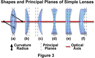
Negative lens elements are the bi-concave (Figure 3(d)), plano-concave (Figure 3(e); with a single planar surface), and concave-meniscus (Figure 3(f)), which also has concave and convex surfaces, but with the center of the lens being thinner than the edges. For both positive and negative meniscus lenses, the distances between the surfaces and their focal planes are unequal, but their focal lengths are equal. The line connecting the centers of the lens curved surfaces in Figure 3 is known as the optical axis of the lens. Simple lenses having a symmetrical shape (bi-convex or bi-concave) have principal planes, denoted by dotted lines in Figure 3, that are equally spaced with respect to each other and the lens surfaces. Curvature radii of the two convex surfaces for a bi-convex lens are indicated by black arrows in Figure 3(a). The lack of symmetry in other lenses, such as the meniscus lenses and the plano negative and positive lenses, causes the locations of the principal planes to vary according to lens geometry. Plano-convex and plano-concave lenses have one principal plane that intersects the optical axis, at the edge of the curved surface, and the other plane buried inside the glass. The principal planes for meniscus lenses lie outside the lens surfaces.
Bi-concave lenses (Figure 3(d)) are primarily utilized for diverging light beams and image size reduction, as well as increasing optical system focal lengths and collimating converging light beams. Often termed the double-concave lens, this optical element refracts parallel input rays so that they diverge away from the optical axis on the output side of the lens, forming a negative focal point in front of the lens. Although the output light rays do not actually unite to form a focal point, they do appear to be diverging from a virtual image located on the object side of the lens. Bi-concave lenses can be coupled to other lenses to reduce optical system focal lengths.
The plano-concave lens illustrated in Figure 3(e) is a divergent element that has a negative focal point and produces a virtual image. When a collimated light beam is incident on the curved surface of a plano-concave lens element, the exit side will form a divergent beam. This beam will appear to emerge from a smaller virtual point source than if the planar lens surface had faced the collimated light beam. Plano-concave lenses, which feature minimal spherical aberration when the concave surface is facing the longest conjugate distance, are employed to expand light beams or to increase focal lengths in existing optical systems.
Also referred to as a convexo-concave lens, the negative (divergent) meniscus lens can be designed to reduce or eliminate additional spherical aberration or coma in optical systems to which the lens is coupled. Meniscus lenses (both positive and negative) are often employed to shorten the focal length of a doublet (two lens elements cemented together) or a plano-convex lens operating at an infinite conjugate ratio (illuminated by parallel light rays). The desired focal length of the final system determines the particular dimensions and character of the meniscus lens that should be added. Plano-convex/meniscus lens combinations display up to four times greater resolution than a plano-convex lens working alone.
Geometrical Construction of Ray Diagrams
Discover how two representative light rays can establish the parameters of an imaging scenario through the application of geometrical optics to determine the size and location of images formed by a lens or multi-lens system.
A lens operates by refracting the incoming light wavefronts at points where they enter and exit the lens surfaces. The angle of refraction, and therefore the focal length, will be dependent upon the geometry of the lens surface as well as the material used to construct the lens. Materials with a high index of refraction will have a shorter focal length than those with lower refractive indices. For example, lenses made of synthetic polymers, such as Lucite (refractive index of 1.47), have a lower refractive index than glass (1.51) leading to a slightly longer focal length. Fortunately, the refractive indices of Lucite and glass are so close together that Lucite can be used in place of glass in many lens applications, including the popular Film-in-a-box cameras that are currently enjoying widespread consumer use. A lens made of pure diamond (refractive index of 2.42) would have a focal length significantly less than either glass or Lucite, although the high cost of pure diamond would be prohibitive for lens construction.
As mentioned above, all lenses have two principal planes that are associated with the front and rear surfaces of the lens. In microscopes, lenses are often cemented together to form larger groups (thick lenses) that have quite unusual locations for the principal planes with respect to the lens surfaces. However, regardless of the number of lens elements or the complexity of the lens system, the location of the principal planes in thick lenses can be determined by tracing light rays through accurate drawings of the lenses. Modern lens designers and optical engineers use sophisticated computer programs to model, design, and trace light rays through individual lenses and multi-element lens systems. These software programs are used to design cameras, telescopes, microscopes, and other optical devices that rely on glass (or plastic) lenses to form images.
There are three general rules that apply to tracing light rays through a simple lens (see Figure 2), which make the task relatively simple. First, a light ray is drawn through the center of the lens from a point on the object to a corresponding point on the image (the tip of the arrows in Figure 2). This ray is not deviated by the lens. Second, a light ray emanating from the uppermost point of the object is sketched parallel to the optical axis and, after being refracted by the lens, will intersect and pass through the rear focal point. In fact, all light rays that are traveling parallel to the optical axis will pass through the rear focal point after being refracted by the lens. Third, a ray from the object passing through the front focal point will be refracted by the lens in a direction that is parallel to the optical axis and coincides with an identical point on the image. The intersection of any two of the rays just described, which are often called characteristic rays, will define the image plane of the lens.
Extending the concept of individual ray traces to a light beam is necessary to describe optical events occurring in the microscope. When a parallel beam of light passes through a simple lens, the rays are refracted and concentrated into a focused spot of light at the focal point (point F in figure 2) of the lens. Alternatively, when light from a point source located at the focal point of a lens enters the lens, it emerges as a paraxial, parallel beam of light. Light from the microscope illumination source can be considered as a train of light waves that are vibrating in phase with each other. The wavefront associated with this wave train lies in a plane that is perpendicular to the direction of propagation (usually parallel to the optical axis of the microscope), and is converted to a spherical wave when passed through a simple bi-convex lens. The radius of the spherical wave is centered at the focal point of the lens, and the light waves all arrive in phase and undergo constructive (additive) interference with each other at the focal point. As is the case for a point source of light, a spherical wavefront emanating from the focal point of a simple lens is converted into a plane wavefront by refraction that occurs when passing through the lens.
A plane wavefront traveling through space is often not perpendicular to the optical axis of a lens, but rather arrives at some angle of incidence that is tilted from the axis. The center of the spherical wave that results from passage of the off-axis plane wave through the lens is located at some point away from the optical axis of the lens. For all practical purposes, a plane wave can be considered to be a spherical wave of infinite radius, which can be focused by a lens into another spherical wave having a much smaller radius that is equal to the focal length of the lens. Thus, it can be concluded that a simple bi-convex lens operates by converting one spherical wave into another spherical wave, often with a different radius (or focal point). In addition, the center of curvature of the second spherical wave lies in the focal plane of the lens.
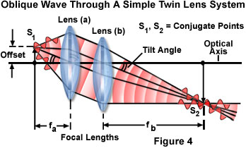
If a point source of light emitting a spherical wave does not lie in the focal plane of the lens (in effect, the light wave is oblique to the optical axis), the lens can then be described as being composed of two separate lenses, as illustrated in Figure 4 for a red monochromatic (single color) point source. Each lens has a different focal length (f(a) for the lens nearest the point source in Figure 4 and f(b) for the second lens), and the spherical wave that emerges from the second lens (lens (b)) is centered at a focal point that is also removed from optical axis of the lens system. As a result, the spherical wave centered at point S(1) in Figure 4 is converted by the first lens into a plane wave that is tilted with respect to the lens axis by the same angle as the point source. The second lens converts the plane wave emerging from the first lens into another spherical wave having a curvature radius centered at point S(2), which is also tilted at the same angle as the point source. In short, the simple lens (which is the sum of two hypothetical component lenses as described in Figure 4) focuses point source S(1) onto point S(2) and vice versa. In optical terms, points S(1) and S(2) are known as conjugate points, and are of fundamental importance to understanding events occurring in the microscope optical train.
Perfect Two-Lens System Characteristics
Explore how a point source of light that does not lie in the focal plane of a lens can be represented as a perfect lens by a system composed of two individual lens elements.
To extend the idea of conjugate points a bit further, if point S(1) is considered to belong to a set of points lying in a plane that is perpendicular to the optical axis of the lens, then the lens would focus each point onto a similar conjugate point in a plane containing the point set S(2). Therefore, by reciprocity, the lens would also focus every point in plane S(2) onto the corresponding point in set S(1) from the original plane. These closely related focal planes are referred to as conjugate planes, and are in simultaneous focus. In general, a microscope has two sets of conjugate planes: one set containing apertures that control the amount of light passing through the optical system, and another set that forms the image.
Because a propagating light wave can be discussed in terms of a wave train, a bundle of rays can be represented by ray traces that are oriented normal to wavefronts. Taking this fact into consideration, the twin lens system discussed in Figure 4 can be reduced to a schematic drawing of ray traces, such as that presented in Figure 2, in order to apply the rules of geometrical construction to determine the size and location of images formed by a lens. As discussed above, two representative light rays, one paraxial (parallel) to the optical axis, and one passing through the center of the lens are all that is necessary to determine these parameters.
The distances a and b in Figure 2 (f(a) and f(b) in Figure 4) and the rear focal length (f) of the lens are related to each other by the simple equation at applies to all thin lenses:
From this equation, it is evident that if the rear focal length and the distance between the lens and the object are known, then the distance between the lens and the focal plane can be calculated. Furthermore, the height of the image produced by the lens divided by the height of the object determines the lateral magnification (M) of the lens:
Of course, the equations just described are based on the assumption that the lens system is surrounded by air on both sides, but this is often not the case in optical microscopy when using oil, water, or glycerin immersion objectives. However, a majority of the common microscope low to medium power objectives do not use an imaging medium other than air. Among the conclusions that can be derived from the simple lens mathematics just discussed are that the magnification (or reduction in size) of an image is equal to the focal length of the lens system, divided by the distance between the object plane and the focal plane on the front side (object side) of the lens. In addition, the magnification (or reduction) of the image is equal to the distance between the image plane and the focal plane on the right side of the lens, divided by the focal length of the lens. These equations are often utilized for the calculation of magnification or reduction in image size by a lens system having a fixed focal length. They are also useful for determining the distance of the image from the principal plane on the right (image space) side of the lens when the specimen is placed at a fixed distance in the object space.
Another factor that is important in microscopy is the longitudinal or axial magnification, which is defined as the ratio of the distance between two image points along the axis of the lens to their corresponding conjugate points in the specimen. In general, the magnitude of longitudinal magnification is determined by the square of the lateral magnification for small distances within the image plane.
Conclusions
Single lenses capable of forming images (like the bi-convex lens) are useful in tools designed for simple magnification applications, such as magnifying glasses, eyeglasses, single-lens cameras, loupes, viewfinders, and contact lenses. The simplest doublets (two-lens systems) are known as achromatics and consist of two lens elements cemented together in order to correct for on-axis spherical and chromatic aberrations. Achromatic doublets usually consist of a bi-convex lens coupled to a positive or negative meniscus lens or to a plano-convex lens. Triplet achromats (containing three lens elements) are utilized as high-power magnifiers and relay lenses. More highly corrected for aberration than doublets, triplet lens combinations are usually optimized through computer design techniques to virtually eliminate distortion. More complex devices often employ a combination of many lens components to enhance the magnification and take advantage of other optical properties of the image. These include microscopes, telescopes, periscopes, cameras, and binoculars, which are are among the many devices using compound optical systems.
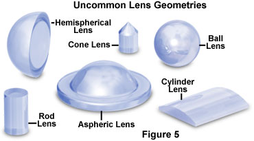
In addition to the common geometries described above, lenses are also produced in a wide variety of other shapes and dimensions (see Figure 5). Spherical ball lenses exhibit equal properties from all incident angles, and have a focal length that depends only on the diameter and the refractive index. By manipulating these two variables, a wide spectrum of focal lengths can be achieved with ball lenses, but their primary application is to improve signal coupling between fibers, emitters, and detectors utilized in the telecommunications industry. Half-ball lenses, which are hemispherically shaped, are useful in fiber communication optics, endoscopy, microscopy, and laser measurement systems. Drum lenses are produced from ball lenses by axial grinding techniques that eliminate a significant portion of the lens radius. These modified lenses are much easier to mount and align in optical systems than their ball lens counterparts.
Cylinder lenses, which are produced in a wide variety of shapes and dimensions, consist of a portion of a cylinder flattened on one surface to focus light in a single plane. Because these lenses are capable of magnification in a single direction, they can be utilized to stretch images. In addition, cylinder lenses can transform a point light source into a line image, making them useful as laser line generators or to focus light into a slit. Other lens shapes include cone, rod, and aspheric optical elements. Cone lenses are employed for 360-degree illumination and image processing applications. With an optical performance similar to cylinder lenses, rod lenses will focus collimated light passing through the diameter into a line. Aspherical lenses, which can be produced in a large variety of numerical apertures, eliminate spherical aberrations and improve focusing and collimating accuracy. These lenses are often utilized in high efficiency illumination systems as condenser elements.
Optical components that form images in the microscope optical train are the illuminator (condenser) lens, the focusing lenses (objective), and the eyepiece lens. Although not generally described as imaging components, the imaging properties of these individual lens elements and groups are of fundamental importance in determining the final quality of the images produced by the microscope.